Stent with anchors to prevent vulnerable plaque rupture during deployment

Inactive Publication Date: 2007-08-21
ABBOTT CARDIOVASCULAR
View PDF246 Cites 140 Cited by
  • Summary
  • Abstract
  • Description
  • Claims
  • Application Information

AI Technical Summary

Benefits of technology

[0008]The present invention is directed to an intravascular stent that can be used to treat a lesion with vulnerable plaque by reducing the fibrous cap stresses. The present invention stent in one embodiment provides staged balloon expansion through stronger and weaker regions in the circumference of the stent, and includes anchors positioned at the circumferential transition between the stronger and weaker regions. During implantation, the anchors radially orient and span the weaker region that overlies the fibrous cap of the vulnerable plaque. When embedded in the shoulder area of the fibrous cap, the anchors decouple luminal expansion from stent expansion within defined regions of the fibroatheroma. As a result, the embedded anchors prevent high expansion forces in the weak region from reaching the fibrous cap thus reducing the chance of cap rupture.
[0013]The rings and links can have various configurations. In one embodiment, each of the rings making up the stent has a proximal end, a distal end, and a cylindrical outer wall surface that extends longitudinally between the proximal end and the distal end of the ring. The rings typically are formed from a plurality of peaks and valleys, where the valleys of one ring are circumferentially in phase with the valleys of an adjacent ring. In this embodiment, at least one link attaches each ring to an adjacent ring so that the links are positioned substantially within one of the valleys and attaches the valley to an adjacent valley. While the rings and links generally may or may not have started out as discrete parts, they have been referred to here as rings and links for convenience. The rings can be thought of as comprising a series of U-, W- and Y-shaped structures in a repeating pattern. While the rings are not necessarily divided or segmented into U's, W's and Y's, the wavy patterns of the rings do resemble such forms. The U's, W's and Y's promote flexibility in the stent primarily by flexing and by tipping radially outwardly as the stent is delivered through a patient's often tortuous anatomy.
[0014]Preferably, the links are positioned to be within the curved part of the W-shaped portion to generally increase the amount of vessel wall coverage. Since the link does not expand appreciably when the stent is expanded, it provides good vessel wall coverage even as the curved part of the W-shaped portion spreads apart as the stent is expanded.
[0016]The stents of the embodiments described above may also be made from a superelastic alloy with the shape memory set in a crimped configuration thereby making the stent self-contracting at body temperature of the patient. Accordingly, the contraction forces of the stent cause the stent to grip onto the balloon.

Problems solved by technology

Currently, the treatment of unstable or vulnerable plaque presents a significant therapeutic challenge to medical investigators.
With the rupture of fibroatheroma forms of vulnerable plaque, the luminal blood becomes exposed to tissue factor, a highly thrombogenic core material, which can result in total thrombotic occlusion of the artery.
In the erosive form of vulnerable plaque, mechanisms of thrombosis are less understood but may still yield total thrombotic occlusion.
Although rupture of the fibrous cap in a fibroatheroma is a major cause of myocardial infarction (MI) related deaths, there are currently no therapeutic strategies in place to treat these lesions that could lead to acute MI.
Since the strains are uniform, the fibrous cap may have a tendency to rupture because it is typically quite thin and is susceptible to the expansion forces of the stent.
Thus, one disadvantage of presently designed intravascular stents is the possibility of the stent, which expands uniformly, imparting expansion forces on the fibrous cap to the degree of rupturing the cap, and inadvertently releasing the lipid pool comprising vulnerable plaque.

Method used


Image

  • Stent with anchors to prevent vulnerable plaque rupture during deployment
  • Stent with anchors to prevent vulnerable plaque rupture during deployment
  • Stent with anchors to prevent vulnerable plaque rupture during deployment

Examples


Embodiment Construction

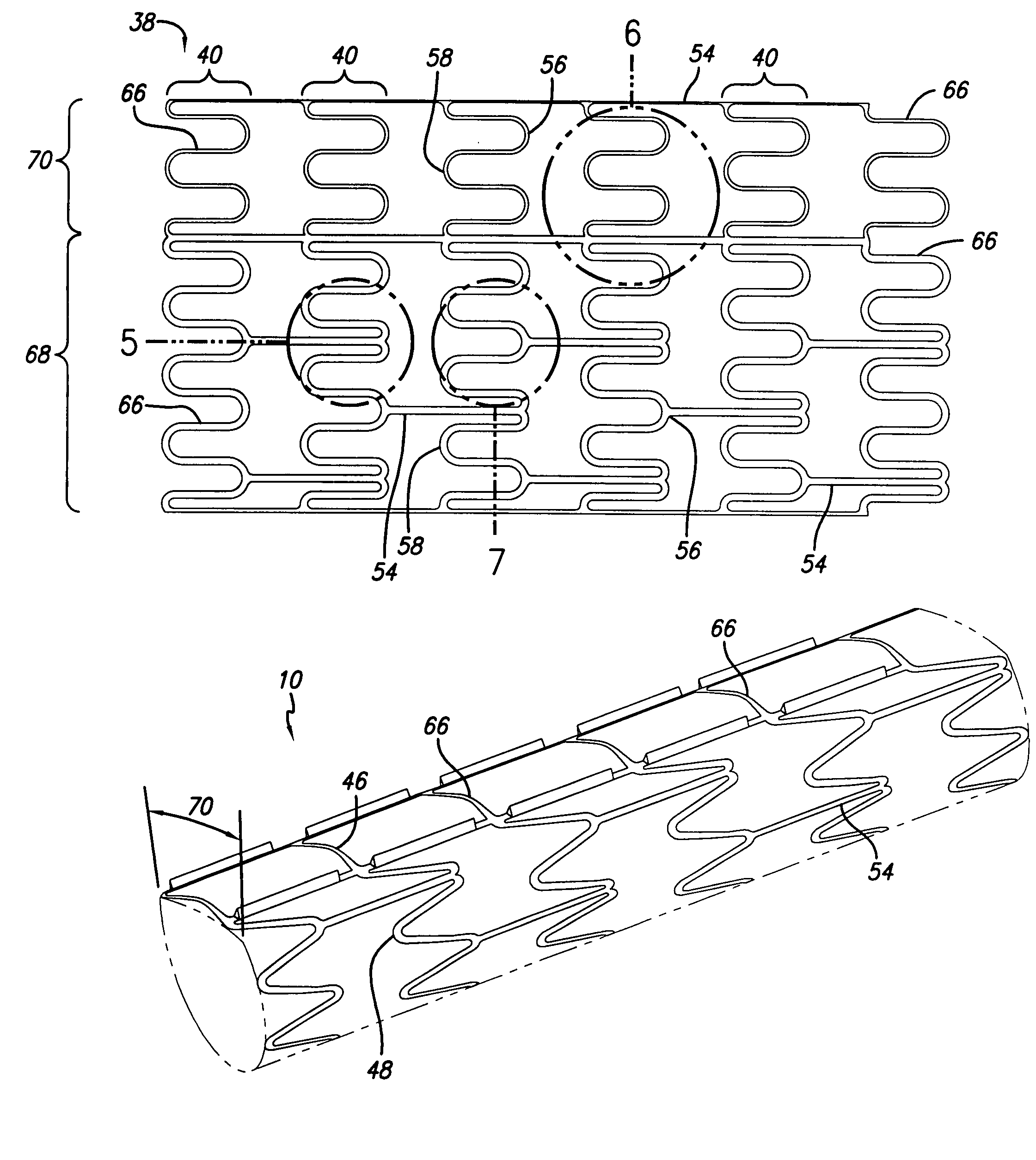
[0045]The present invention is directed to an intravascular stent that can be used to treat a lesion with vulnerable plaque by minimizing the cap stresses during stent expansion. The present invention stent in one embodiment provides staged balloon expansion through stronger and weaker regions in the cylindrical wall of the stent, and includes anchors positioned at the circumferential transition between the stronger and weaker regions. During implantation, the anchors radially orient and span the weaker region over the vulnerable plaque during the staged expansion. This minimizes cap stresses and reduces the chance of cap rupture.

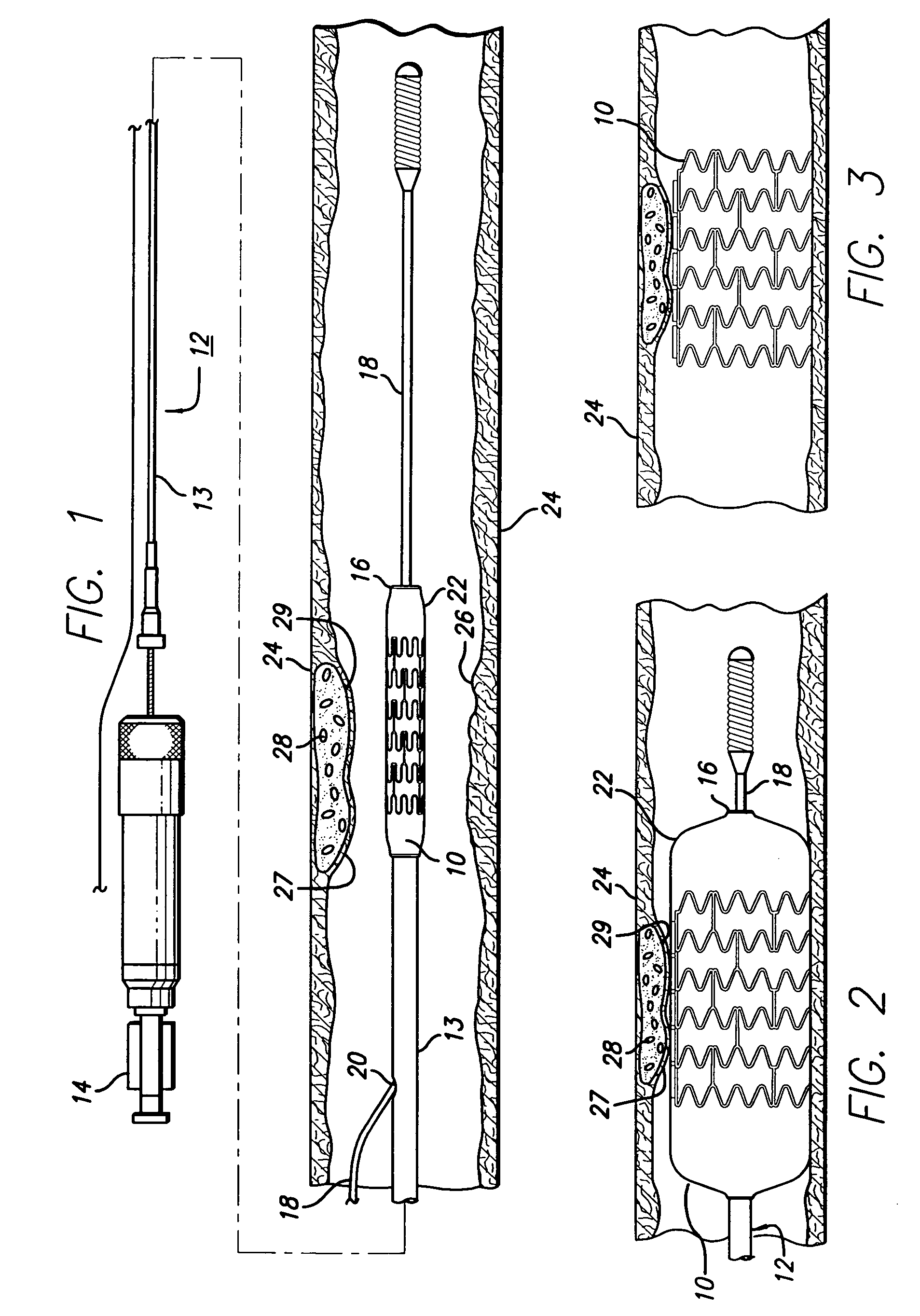
[0046]Turning to the drawings, FIG. 1 depicts one embodiment of the present invention stent 10 mounted on a catheter assembly 12 which is used to deliver the stent and implant it in a body lumen, such as a coronary artery, peripheral artery, or other vessel or lumen within a patient's body. The catheter assembly 12 includes a catheter shaft 13 which has a p...


PUM


Abstract

A stent for implantation in a body lumen for protecting from rupture a fibrous cap in order to treat vulnerable plaque. One embodiment of the stent achieves staged expansion through stronger and weaker circumferential regions, and includes optional anchors positioned at the circumferential transition between the stronger and weaker regions. During the first stage expansion, the weaker region expands moving the anchors laterally apart. The anchors straddle the fibrous cap and embed into the vessel wall. The second stage expansion of the stent exerts gentler stresses by the weaker region against the fibrous cap while the stronger region exerts greater stresses on the remainder of the vessel wall to open the vessel.

Description

BACKGROUND OF THE INVENTION[0001]The present invention relates to vascular repair devices, and in particular to intravascular stents, which are adapted to be implanted into a patient's body lumen, such as a blood vessel or coronary artery, for the treatment of unstable or vulnerable, human atherosclerotic plaque.[0002]Currently, the treatment of unstable or vulnerable plaque presents a significant therapeutic challenge to medical investigators. Vulnerable plaque is characterized by a basic lesion which is a raised plaque beneath the innermost arterial layer, the intima. Atherosclerotic plaques are primarily composed of varying amounts of long chain extracellular matrix (ECM) proteins that are synthesized by smooth muscle cells. The other primary lesion component of atherosclerotic plaque includes lipoproteins, existing both extracellularly and within foam cells derived primarily from lipid-laden macrophages. In a more advanced lesion, a necrotic core may develop, consisting of lipid...

Claims


Application Information

Patent Timeline
IPC IPC(8): A61F2/06
CPCA61F2/91A61F2/915A61F2/89A61F2/848A61F2002/91508A61F2002/91516A61F2230/0054A61F2002/91575A61F2220/005A61F2230/0013A61F2002/91533
Inventor COX, DANIEL L.FEEZOR, CHRISTOPHER
Owner ABBOTT CARDIOVASCULAR
Why Eureka
Try Eureka