Digital audio data reproducing system
a digital audio and reproducing technology, applied in the field of digital audio data reproducing system, can solve the problems of troublesome work, inability to instantly exchange the scratch reproduction of the usual analog record for the reproduction of the specific analog record, etc., and achieve the effect of significantly simplifying the operation of the audio signal, facilitating adaptation, and facilitating the operation of the scratch reproduction
- Summary
- Abstract
- Description
- Claims
- Application Information
AI Technical Summary
Benefits of technology
Problems solved by technology
Method used
Image
Examples
embodiment 1
(Embodiment 1)
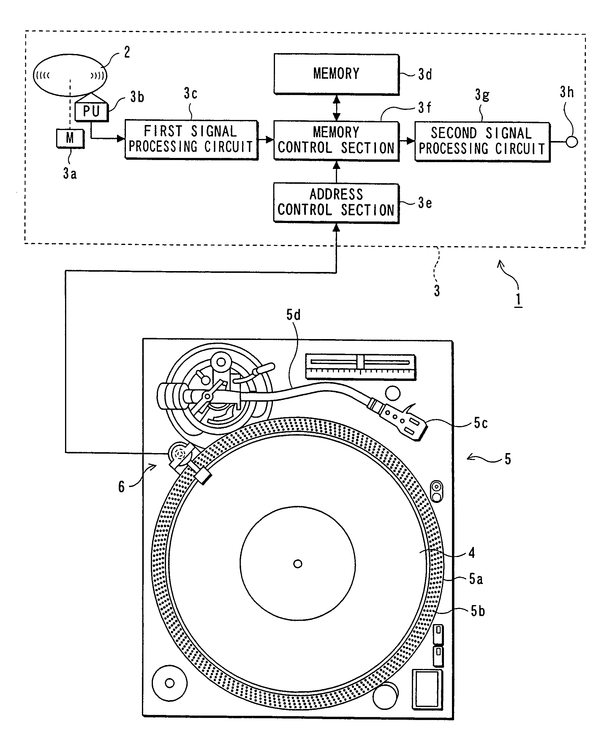
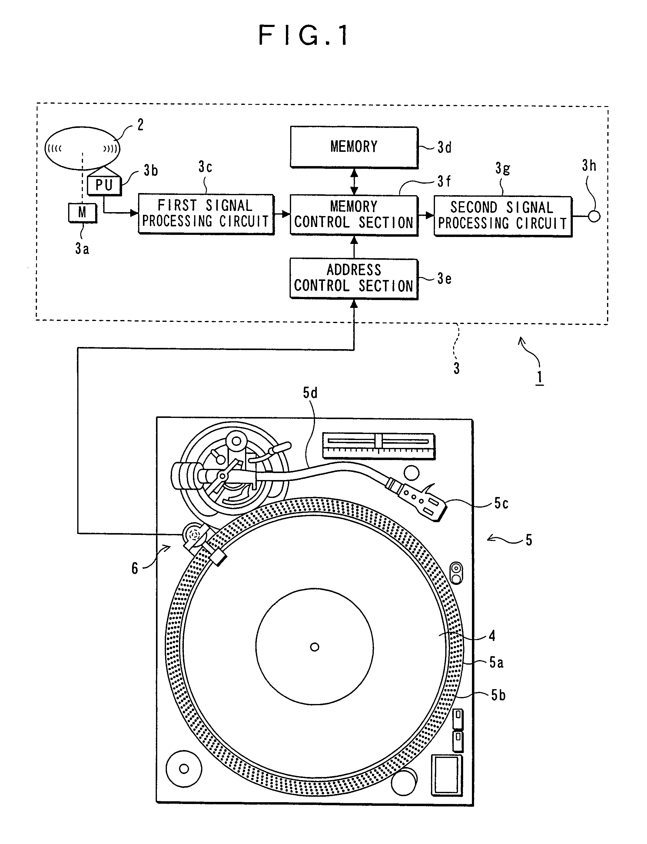
[0031]FIG. 1 is a block diagram schematically showing a scratch reproduction system in which a rotation detecting apparatus according to a first embodiment of the invention is used.
[0032]In the scratch reproduction system 1, a data reproduction apparatus 3 is controlled in such a manner that it reproduces audio data in accordance with the scratch operation of an analog record player 5. As shown in FIG. 1, the scratch reproduction system 1 comprises an optical disk 2, a data reproduction apparatus 3, an analog record 4, an analog record player 5 and the rotation detecting apparatus 6.
[0033]The optical disk 2, in which audio data are stored, is realized by a compact disk, a mini disk having a 64 mm diameter, or the like. The data reproduction apparatus 3 is used as an apparatus for reproducing the audio data stored in the optical disk 2. The data reproduction apparatus 3 comprises a spindle motor 3a for rotating the optical disk 2, an optical head 3b for reading the audi...
embodiment 2
(Embodiment 2)
[0050]FIG. 8 is a schematic diagram showing a scratch reproduction system in which a rotation detecting apparatus according to a second embodiment is installed. In this case, the same reference numeral is used for each of the same elements as those in FIGS. 1-7, and the description thereof is omitted.
[0051]A rotation detecting apparatus 11 comprises a detecting section 12 and a switching section 13, as shown in FIG. 8. The detecting section 12 includes an image sensor 12a, a delay circuit 12b and a comparator 12c.
[0052]The image sensor 12a is capable of reading data in the analog record 4 as image data. Light irradiates the label surface 4b of an analog record 4 and the image sensor 12a always receives the light reflected therefrom to form image data, and then image data are supplied to the delay circuit 12b and the comparator 12c. The delay circuit 12b supplies the image data delayed in a predetermined time, and the comparator 12c detects the speed of revolution and ...
PUM
| Property | Measurement | Unit |
|---|---|---|
| diameter | aaaaa | aaaaa |
| speed | aaaaa | aaaaa |
| time | aaaaa | aaaaa |
Abstract
Description
Claims
Application Information
 - R&D
- Intellectual Property
- Life Sciences
- Materials
- Tech Scout
- Unparalleled Data Quality
- Higher Quality Content
- 60% Fewer Hallucinations
Browse by: Latest US Patents, China's latest patents, Technical Efficacy Thesaurus, Application Domain, Technology Topic, Popular Technical Reports.
© 2025 PatSnap. All rights reserved.Legal|Privacy policy|Modern Slavery Act Transparency Statement|Sitemap|About US| Contact US: help@patsnap.com


