Suspension for microphones

a microphone and suspension technology, applied in the direction of transducer types, color television, television systems, etc., can solve the problems of reducing sound quality, difficult for the boomer to determine when the microphone is close,

Inactive Publication Date: 2007-07-31
JAN JUHLER +1
View PDF10 Cites 4 Cited by
  • Summary
  • Abstract
  • Description
  • Claims
  • Application Information

AI Technical Summary

Problems solved by technology

The microphone may not be dropped into the field of vision and it is very difficult for the boomer to determine when the microphone is close to or is in the field of vision.
As it is difficult for the boomer to keep the microphone still during recording, there will always be some vibrations in the microphone, which reduce the sound quality.

Method used


Image

  • Suspension for microphones
  • Suspension for microphones
  • Suspension for microphones

Examples


Embodiment Construction

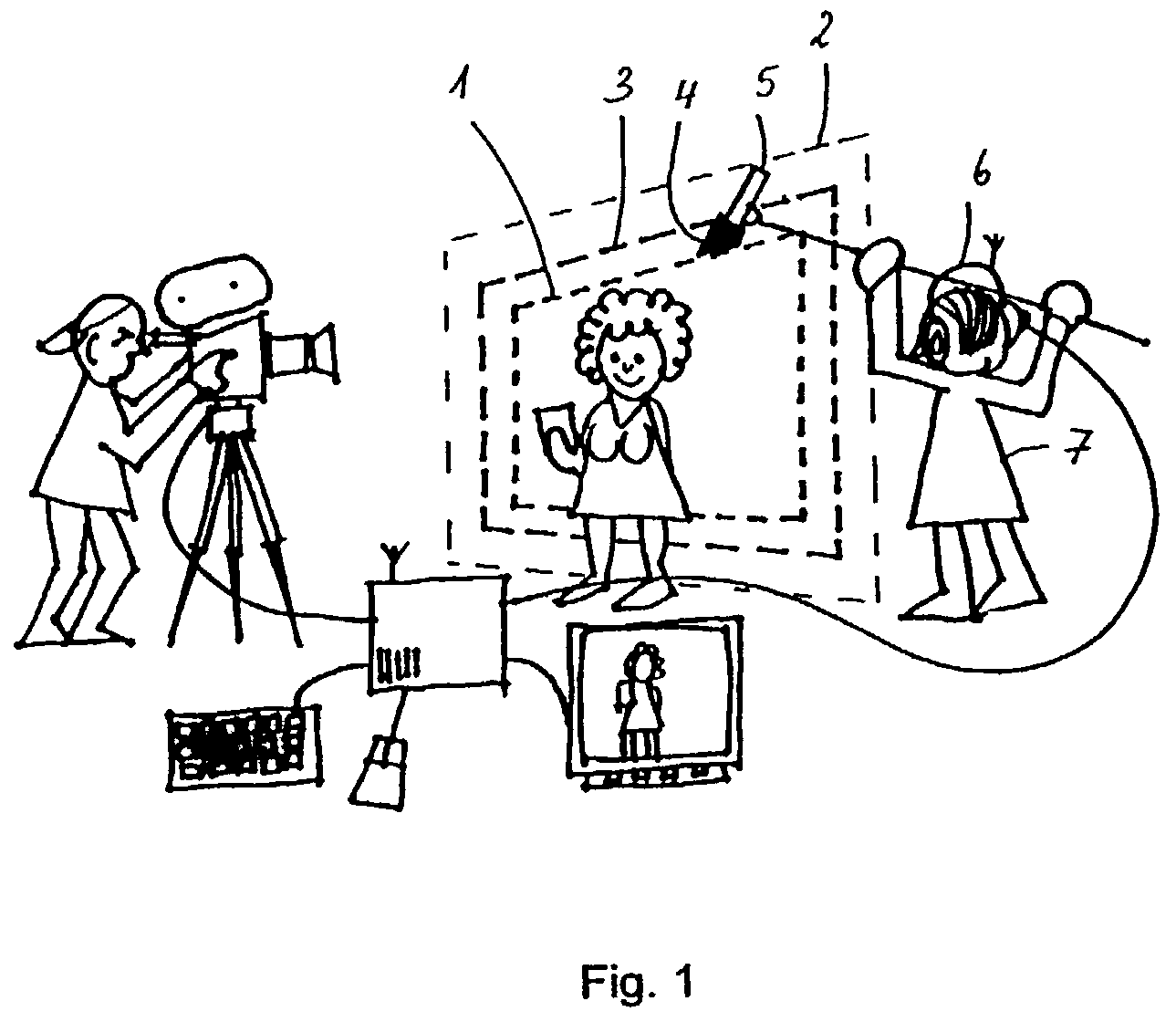
[0007]It is an object of the present invention to provide a system for avoiding unwanted objects in a field of vision, so as to make it easier for the boomer to control the movement of the microphone and so as to ensure that the film or a part thereof is not destroyed due to unwanted objects in the field of vision.

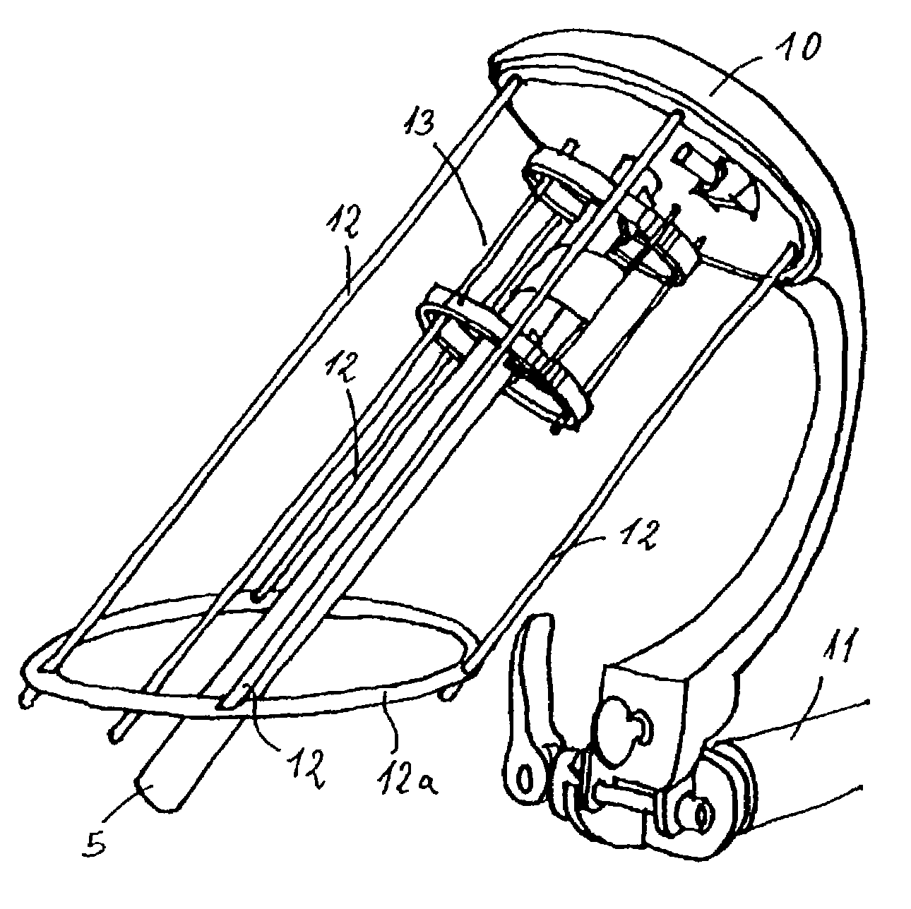
[0008]It is a further object of the present invention to provide a suspension for a microphone, which absorbs the vibrations from the boom, and wherein a plurality of microphones can be suspended.

[0009]It is a further object of the present invention to provide a wind hood for a microphone, wherein the wind effect on the microphone is reduced to a minimum, and which allows for as free passage for the sound waves to the microphone as possible.

[0010]According to a first aspect, the present invention relates to a system for avoiding unwanted objects in a field of vision and comprising:[0011]a field of vision defining a predetermined picture format / size,[0012]a search field,[00...


PUM


Abstract

A microphone suspension, particularly for absorbing the vibrations from a boom. The microphone suspension has a base member pivotable mounted to the boom. Bars extend substantially perpendicular to the base member and are adapted to hold an internal microphone holder by first elastic members. An oval ring-shaped member interconnects the bars in the ends opposite to the base member. At least one microphone can be suspended in the internal holder.

Description

[0001]This application claims priority on provisional Application No. 60 / 331,991 filed on Nov. 23, 2001, the entire contents of which are hereby incorporated by reference.[0002]The invention relates to equipment for shooting of film, and in particular to a system and a method for avoiding objects in a field of vision, to a microphone suspension and to a wind hood for a microphone.BACKGROUND OF THE INVENTION[0003]Sound equipment for shooting of films often comprises a boom with a microphone mounted in the end, and wherein a boomer (the person holding the boom) holds the boom right above the actors in a specific distance therefrom, so as to obtain as good sound on the film as possible. The microphone may not be dropped into the field of vision and it is very difficult for the boomer to determine when the microphone is close to or is in the field of vision.[0004]Prior art describes systems, wherein an active item (such as a diode) is positioned on the microphone and which, via a contro...

Claims


Application Information

Patent Timeline
Patent Type & Authority Patents(United States)
IPC IPC(8): H04R9/08H04N5/222
CPCH04N5/222
Inventor JUHLER, JAN
Owner JAN JUHLER
Why Eureka
Try Eureka