Eureka AIR delivers breakthrough ideas for toughest innovation challenges, trusted by R&D personnel around the world.

Gas-insulated switchgear device

a switchgear and gas-insulated technology, applied in the direction of air-break switch, high-tension/heavy-dress switch, contact mechanism, etc., can solve the problems of environmental impact, large increase of the overall dimension of the substation, and negative impact on installation and maintenance costs, so as to improve the functionality, increase flexibility, and optimise the effect of structur

Active Publication Date: 2007-07-31
HITACHI ENERGY SWITZERLAND AG
View PDF10 Cites 13 Cited by
  • Summary
  • Abstract
  • Description
  • Claims
  • Application Information

AI Technical Summary

Benefits of technology

[0009]Thus, the main aim of the present invention is to provide a high- or medium-voltage gas-insulated switchgear device of the above mentioned type having, with respect to known devices, a further improved functionality and an increased flexibility in terms of electrical operations which can be performed and coordinated, and of operating configurations which can be realized during practical use, with an optimised structure.

Problems solved by technology

According to more traditional solutions, electric substations have been realized by using several components which are structurally independent and suitably connected to each other and to the power line when assembling in order to obtain the required layout and to perform each a respective dedicated function; these traditional solutions have presented some drawbacks in practical use, mainly due to the large number of components required, even for providing a minimal configuration, and to their structural and functional separation.
Indeed, these aspects result in heavy maintenance requirements for each and any of the single components used, and to a considerable increase of the overall dimensions of the substation, with a consequent negative impact on installation and maintenance costs, as well as on environmental impact.
For example, before operating the disconnector unit for disconnecting one or more of the input or output connections, it is usually necessary first to open the interruption unit thus breaking the current flow and therefore putting out of commission the whole device; this is not entirely satisfactory for example when the device has an input connection and two output connections only one of which should be disconnected e.g. for maintenance reasons, while the other connections with the loads connected could be kept working.

Method used


Image

  • Gas-insulated switchgear device
  • Gas-insulated switchgear device
  • Gas-insulated switchgear device

Examples


Embodiment Construction

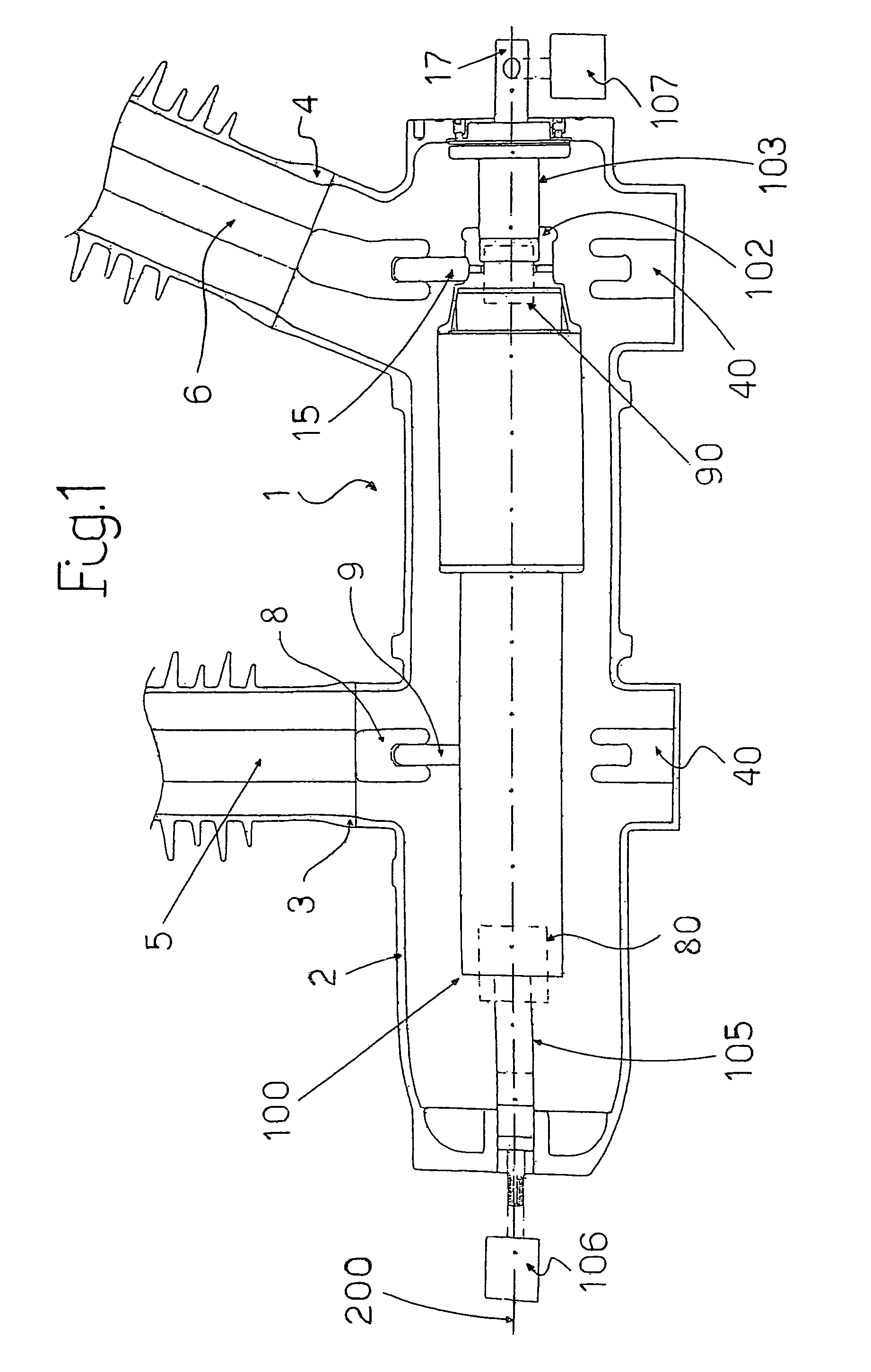
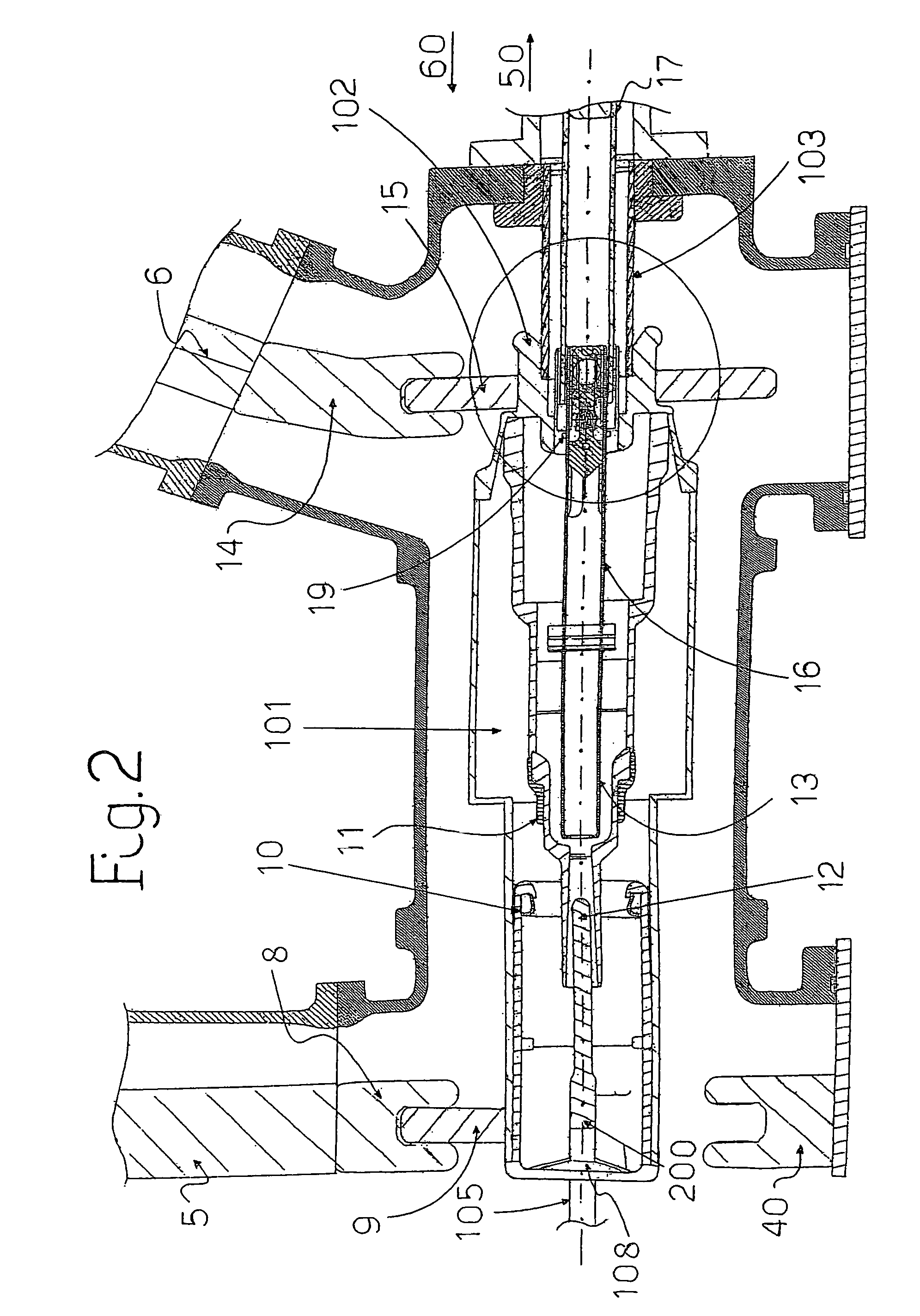
[0016]With reference to the above cited figures, the high- or medium-voltage gas-insulated switchgear device according to the invention, comprises a first fixed casing 1 which is partially or totally filled with an electric insulating gas, e.g. SF6, and has, in the embodiments illustrated, a pod-shaped portion 2 and one or more bushings mechanically mounted on the pod-shaped portion 2. Each bushing contains a corresponding electrical terminal or bar for input / output connections of the switchgear device with a power line and / or other components, such as transformers, loads, et cetera; in FIG. 1 there are illustrated only two bushings 3 and 4 housing two corresponding terminals 5 and 6, respectively. As schematically shown in FIG. 4, the casing 1 preferably comprises a third bushing 7 housing a corresponding third terminal 70.

[0017]The switchgear device according to the invention also comprises, positioned inside the casing 1, a disconnector unit having at least a first fixed contact ...


PUM


Abstract

A gas-insulated switchgear device comprising a first casing housing: at least a first terminal for input / output connection; a disconnector unit comprising at least a first fixed contact operatively coupled to said first terminal and a corresponding first movable contact which can be electrically connected / disconnected with said first fixed contact, during operation of the disconnector unit; a circuit breaker unit electrically connected to said disconnector unit and comprising at least a couple of interruption contacts which can be actuated, during operation of said circuit breaker unit, between a circuit breaker closed position where they are electrically coupled and a circuit breaker open position where they are electrically separated; actuating means for operating said disconnector unit and said circuit breaker unit; a second casing operatively coupled with said actuating means, which houses said interruption contacts and on the outer surface of which at least said first movable contact is mounted; characterized in that said second casing is pivotally mounted inside said first casing so as to rotate said first movable contact during operation of said disconnector unit, said couple of interruption contacts being operatively coupled to said actuating means so as to be kept electrically coupled in said circuit breaker closed position and substantially still relative to each other during rotation of said second casing.

Description

CROSS REFERENCE TO RELATED APPLICATIONS[0001]This application claims priority under 35 U.S.C. §119 to European Application 04076123.1 filed with European Patent Office on 19 Apr. 2004, the entire contents of which are hereby incorporated by reference in their entireties.FIELD[0002]The present invention relates to a gas-insulated switchgear device for high- or medium-voltage applications, i.e. for voltages above 1000V.BACKGROUND INFORMATION[0003]It is well known in the art that along the path of a power grid there are provided several electric substations for transmitting and distributing electricity from a power generating source to loads and users connected to the feeding grid; these substations may be configured according to different layouts depending on the applications, for example in / out or T-type layouts, H-type layouts et cetera, and are realized by using a series of electric components, such as disconnectors, circuit breakers, instrument transformers, control systems.[0004]...

Claims


Application Information

Patent Timeline
IPC IPC(8): H01H33/14H01H33/12H01H33/66
CPCH01H33/122H01H31/003
Inventor CAMERONI, ROBERTOSFONDRINI, LIBEROGARGIONI, VITTORIO
Owner HITACHI ENERGY SWITZERLAND AG
Why Eureka
Eureka Blog
Learn More