
Friction bearing composite material with a metal base layer

a composite material and metal base layer technology, applied in the direction of bearings, rolling resistance optimization, layered products, etc., can solve the problems of fibers not being easily held or anchored in the sliding layer material, unsatisfactory wear resistance, potential fatigue spots, etc., to improve the bonding effect of carbon fibers in the ptfe base material

Active Publication Date: 2007-07-31
GLEITLAGER
View PDF13 Cites 7 Cited by
  • Summary
  • Abstract
  • Description
  • Claims
  • Application Information

AI Technical Summary

Benefits of technology

The invention is a sliding bearing composite material that has improved wear resistance and maintains a low coefficient of friction. The material includes a sliding layer material made of PTFE and a small amount of carbon fibers and PFA. The carbon fibers are held in the material by a bonding process and the addition of PFA further improves the bonding. The material also includes zinc sulfide particles that help separate and homogeneously mix the carbon fibers with the other components. The carbon fibers are held in place by the material and the addition of PPSO2 further improves the bonding. The material has excellent wear resistance and a good coefficient of friction.

Problems solved by technology

However, the wear resistance is unsatisfactory and can be improved by adding fillers, e.g. metallic fillers.
A high carbon fiber portion, in particular 4 percent by volume and more, increases the wear resistance, however, severely impairs the coefficient of friction.
Moreover, the addition of fibrous fillers has the disadvantage that the fibers cannot be easily held or anchored in the sliding layer material and represent potential fatigue spots.

Method used


Image

  • Friction bearing composite material with a metal base layer
  • Friction bearing composite material with a metal base layer

Examples


Embodiment Construction

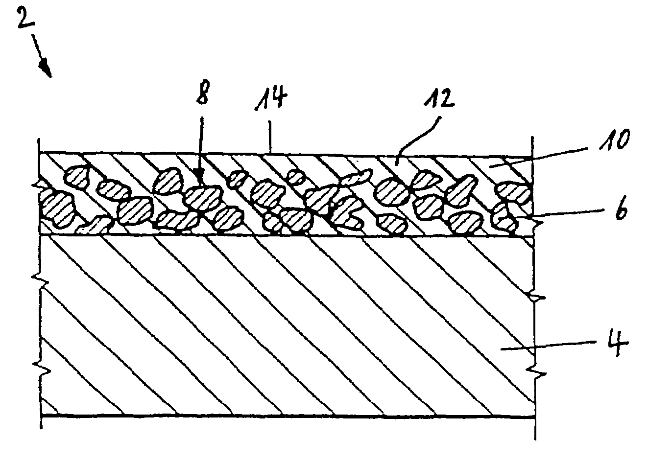
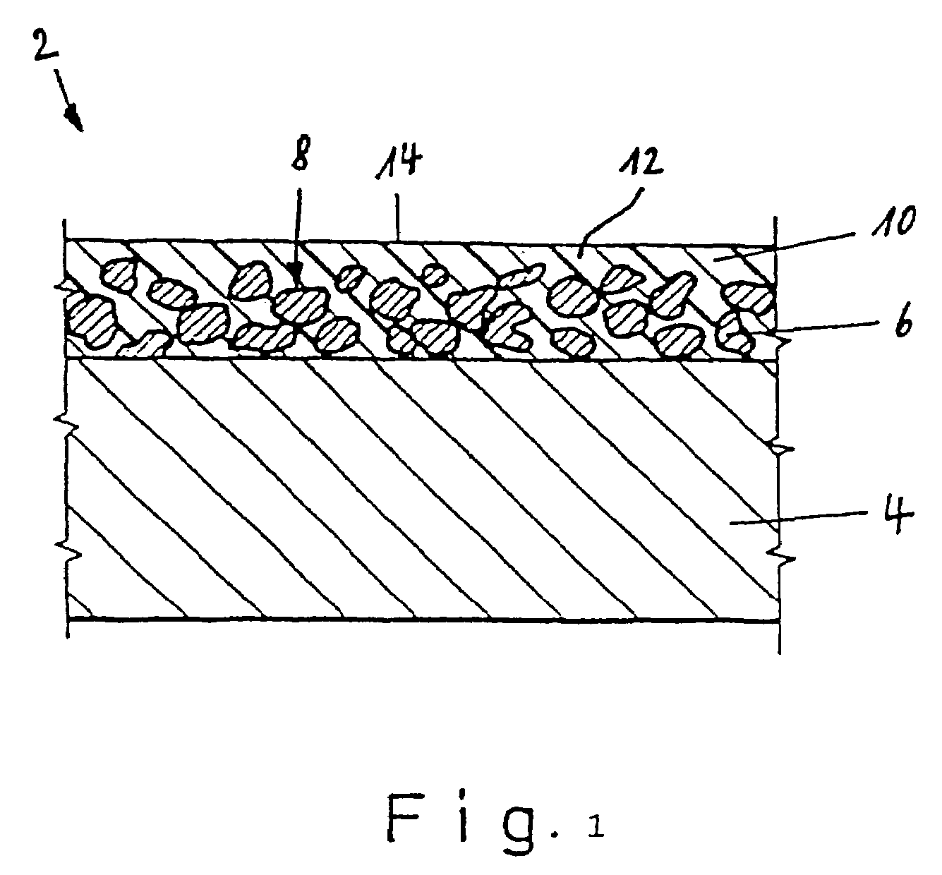
[0025]The sliding bearing composite material, generally referred to with reference numeral 2 in the figure, comprises a metallic support layer 4 of steel and a porous carrier layer 6 disposed thereon, preferably of a lead-free bronze layer, e.g. with 90 percent by weight of copper and 10 percent by weight of tin. A sliding layer material 10 is introduced into the pores of the carrier layer 6 on the upper side 8 of the carrier layer 6 opposite to the support layer 4. The sliding layer material 10 projects slightly past the upper side 8 of the carrier layer 6 and forms a sliding layer 12 with a sliding surface 14 for a sliding partner (not shown). The sliding layer material 10 has a PTFE matrix with at least 60 percent by volume of PTFE and 10 to 25 percent by volume of zinc sulfide and, in accordance with the invention, 1.5 to 3.5 percent by volume of carbon fibers and 1 to 7 percent by volume of PFA.

[0026]A preferred composition of the sliding layer material comprises 65 to 85 perce...


PUM

PropertyMeasurementUnit
grain sizeaaaaaaaaaa
thicknessaaaaaaaaaa

Abstract

A friction bearing composite material comprises a metal base layer, a porous support layer applied thereto, and a low friction layer made from PTFE forming a bearing surface for a bearing partner. The low friction material forming the sliding surface also fills the pores in the support layer and comprises at least 60 vol. % PTFE and 10-25 vol. % zinc sulphide. In order to achieve a high wear resistance with a low coefficient of friction, the low friction material further comprises 1.5-3.5 vol. % carbon fibers and 1-7 vol. % PFA.

Description

[0001]This application is the national stage of PCT / EP02 / 05993 filed on May 31, 2002 and also claims Paris Convention priority of DE 101 26 463.1 filed on May 31, 2001.BACKGROUND OF THE INVENTION[0002]The invention concerns a sliding bearing composite material with a metallic support layer, a porous carrier layer disposed thereon, and a sliding layer on the basis of PTFE which forms a sliding surface for a sliding partner, wherein the sliding layer material forming the sliding layer also fills the pores of the carrier layer and comprises at least 60 percent by volume of PTFE and 10-25 percent by volume of zinc sulfide.[0003]A sliding bearing composite material of this type is disclosed e.g. in EP 0 232 922 B1. This document, however, does not mention a minimum content of 60 percent by volume of PTFE. For some length of time, the Assignee has produced a sliding bearing composite material which consists of 75 percent by volume of PTFE and 25 percent by volume of ZnS. This patent docum...

Claims


Application Information

Patent Timeline
Patent Type & Authority Patents(United States)
IPC IPC(8): F16C33/20B32B15/04B32B27/18
CPCB32B15/04B32B27/18F16C33/201Y02T10/865Y10S384/908Y10S384/902B32B27/20B32B27/322B32B2305/026B32B2327/18B32B5/18B32B2307/554B32B15/046B32B15/085
Inventor BICKLE, WOLFGANGSCHUBERT, WERNERSTORCH, THOMAS
Owner GLEITLAGER
Learn More