
Method and apparatus for reducing velocity errors when writing spiral servo information onto a disk surface

a technology of spiral servo information and velocity error reduction, applied in the field of data storage devices, can solve the problems of significant cost and time savings, high cost and time consumption, and the inability to write spiral servo information onto the disk surface, and achieve the effect of reducing velocity errors

Inactive Publication Date: 2007-07-24
MAXTOR
View PDF22 Cites 19 Cited by
  • Summary
  • Abstract
  • Description
  • Claims
  • Application Information

AI Technical Summary

Benefits of technology

[0030]The present invention is directed to a method and apparatus for reducing velocity errors when writing spiral servo information onto a disk surface of a disk drive.

Problems solved by technology

In general, a STW is a very expensive piece of capital equipment.
Even a small reduction in the amount of data needed to be written by the STW per disk surface can result in a significant cost and time savings.
Using a servo track writer in this manner presents new problems, as prior servo track writers only were required to move the disk drive's write head in small radial steps across the disk surface.
One problem relates to velocity overshoots and undershoots.
However, because of gain variation and other errors, the velocity of the servo track writer's pushpin deviates from the desired velocity trajectory at a transition point between an initial acceleration region and a zero acceleration region, resulting in either velocity overshoots or velocity undershoots.

Method used


Image

  • Method and apparatus for reducing velocity errors when writing spiral servo information onto a disk surface
  • Method and apparatus for reducing velocity errors when writing spiral servo information onto a disk surface
  • Method and apparatus for reducing velocity errors when writing spiral servo information onto a disk surface

Examples


Embodiment Construction

[0040]While this invention is susceptible of embodiments in many different forms, there are shown in the drawings and will herein be described in detail, preferred embodiments of the invention with the understanding that the present disclosure is to be considered as an exemplification of the principles of the invention and is not intended to limit the broad aspects of the invention to the embodiments illustrated.

[0041]Prior to writing spiral servo information onto the disk surface, the write head may be positioned with its actuator arm against a crash stop. That is, the write head will not be over the disk surface or will be in a position very close to the inner diameter or outer diameter of the disk surface.

[0042]In order to quickly bring the write head to a constant velocity over the disk surface, a gain associated with the servo track writer is set so that the servo track writer's pushpin follows a desired velocity trajectory. A diagrammatic representation of a desired velocity t...


PUM


Abstract

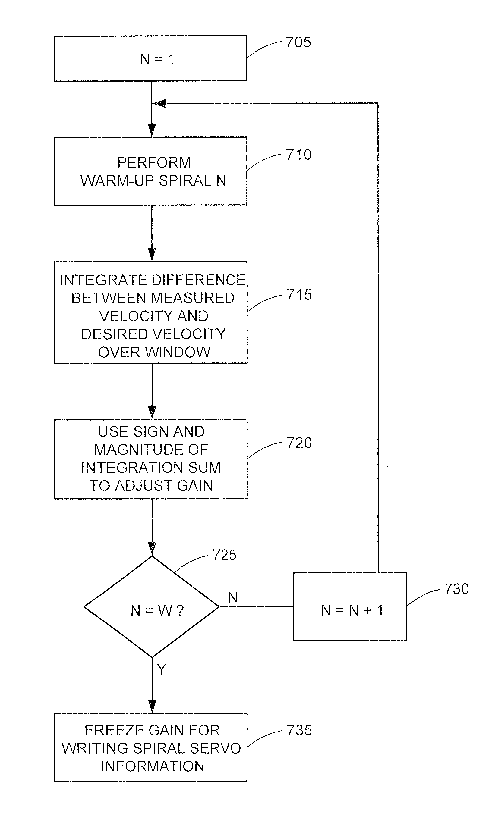
The present invention is directed to a method and apparatus for reducing velocity errors when writing spiral servo information onto a disk surface of a disk drive. In one embodiment, a servo track writer is provided for moving a write head at a controlled velocity. The write head is used to write spiral servo information onto a disk surface. The write head is moved, using the servo track writer, at an actual velocity trajectory to simulate writing one spiral of spiral servo information. Differences between the actual velocity trajectory and a desired velocity trajectory are measured on a control sample by control sample basis over a window of control samples. The differences are integrated over the window. A gain, associated with the servo track writer controlling the velocity of the write head, is adjusted using the integrated differences.

Description

CROSS-REFERENCE TO RELATED APPLICATIONS[0001]Priority is claimed from U.S. Provisional Patent Application Ser. No. 60 / 475,048 filed Jun. 2, 2003, which is incorporated herein by reference in its entirety.FIELD OF THE INVENTION[0002]The present invention relates generally to data storage devices, such as disk drives. More particularly, the present invention relates to a method and apparatus for reducing velocity errors (e.g., velocity overshoot and velocity undershoot) when writing spiral servo information onto a disk surface of a disk drive.BACKGROUND OF THE INVENTION[0003]Computer disk drives store information on magnetic disks. Typically, the information is stored on each disk in concentric tracks that are divided into sectors. Information is written to and read from a disk by a transducer that is mounted on an actuator arm capable of moving the transducer radially over the disk. Accordingly, the movement of the actuator arm allows the transducer to access different tracks. The di...

Claims


Application Information

Patent Timeline
IPC IPC(8): G11B21/02G11B5/596
CPCG11B5/59633G11B5/59638G11B5/59661G11B5/59622
Inventor EVERETT, TIMRIGNEY, BRIAN
Owner MAXTOR
Learn More