
User authentication for contact-less systems

a technology of contact-less systems and user authentication, applied in the field of contact-less access control systems, can solve the problems of volume, expected to arise, and inability to reproduce the encrypted user id required to permit access to the building or the vehicl

Inactive Publication Date: 2007-07-24
BCE
View PDF8 Cites 55 Cited by
  • Summary
  • Abstract
  • Description
  • Claims
  • Application Information

AI Technical Summary

Problems solved by technology

As RFID technology gains widespread usage in an increasing number of industries, at least two problems are expected to arise in the above-described access control context.
The first such problem is related to security, and is especially evident if one imagines the situation where a malicious entity gains access to the database of authorized user IDs.
In this scenario, a malicious entity that gains access to the database of authorized user IDs, but without the secret encryption key, will not be able to reproduce the encrypted user ID required to permit access to the building or vehicle.
The second problem that is expected to arise is one related to volume.
Yet the vast majority of these tag-containing objects are not intended to be submitted to the reader for access control purposes.
Unfortunately, however, the reader has no way of knowing which tags are being intentionally presented to it for access control purposes, and therefore must make the assumption that each tag needs to be authenticated.
The risk of picking up signals emitted by multiple tags can only increase as the RFID industry advances on the standardization front.
However, an issue that is overlooked by these and other prior art proposals is the difficulty caused by the delay resulting from having to perform numerous queries to a database of user IDs, where such database is typically located remotely from the reader.
As a result, the bandwidth between the reader and the database, as well as the computational speed of the database, become significant bottlenecks in the quest for real-time performance in an access control scenario.
These bottlenecks become even more obstructive if the above-described encryption techniques are employed, as the net effect is the introduction of further delay in the process.

Method used


Image

  • User authentication for contact-less systems
  • User authentication for contact-less systems
  • User authentication for contact-less systems

Examples


Embodiment Construction

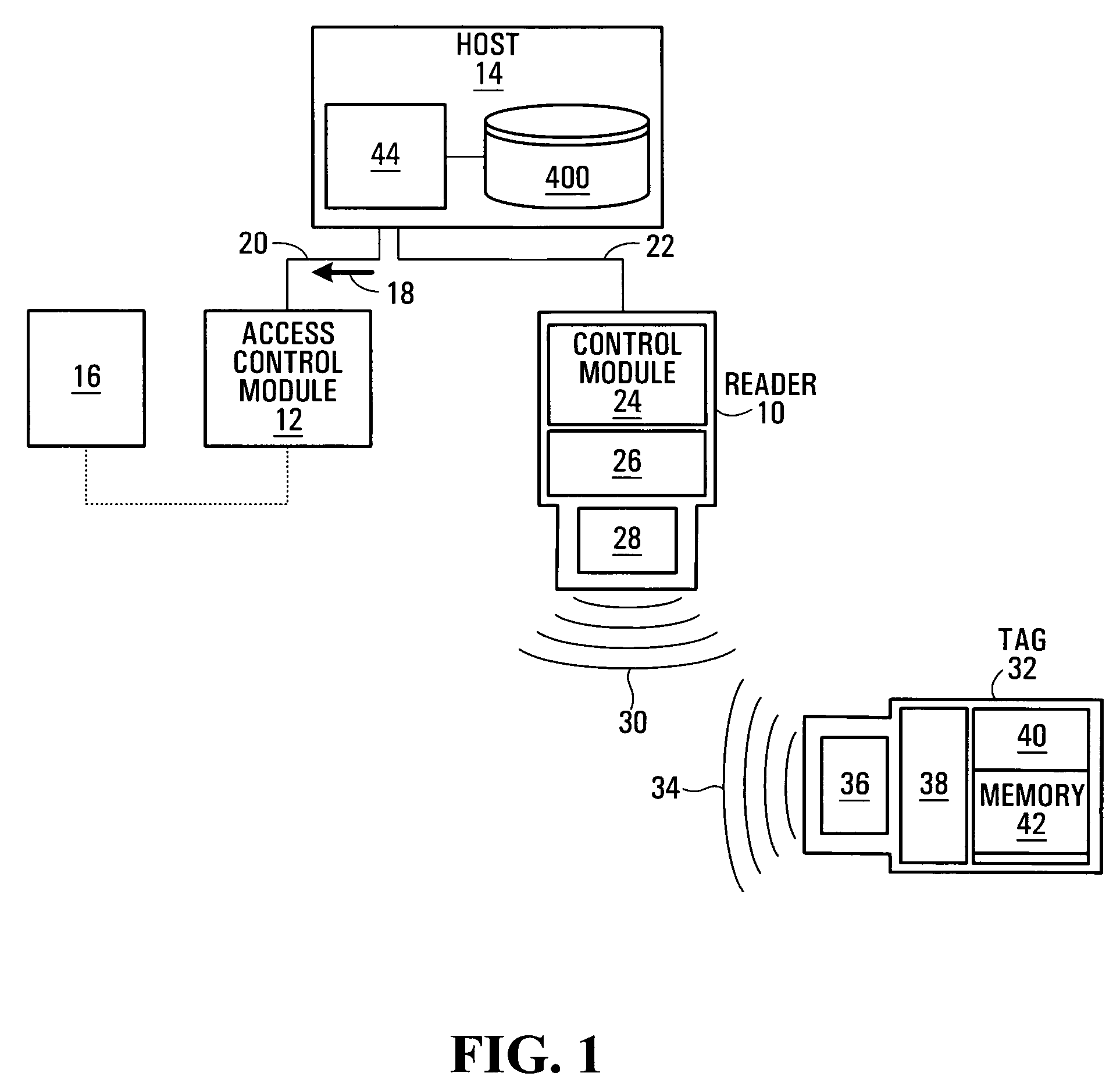
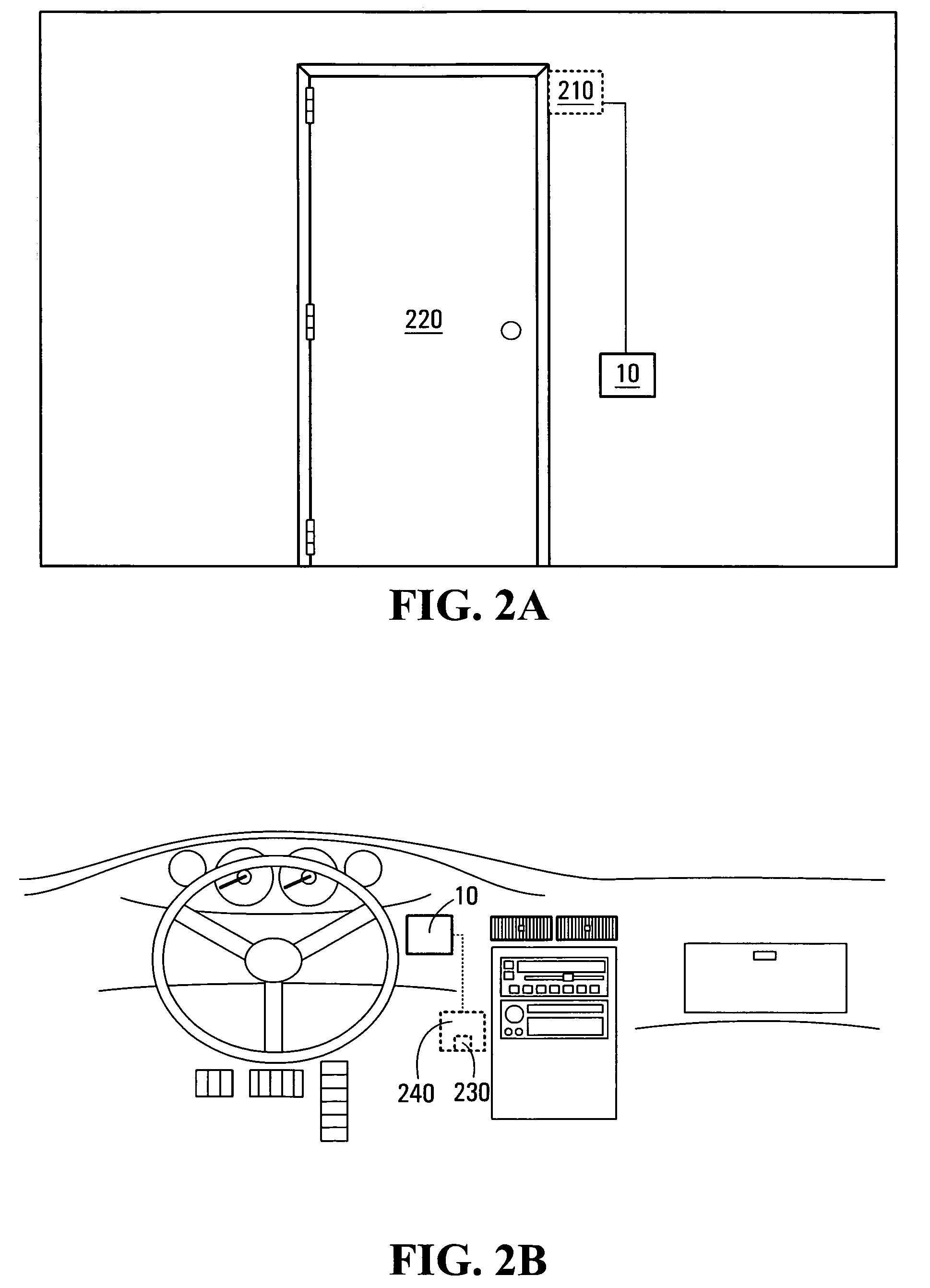
[0028]With reference to FIG. 1, there is depicted an access control system comprising an RFID reader 10 (hereinafter referred to simply as a “reader”), an access control module 12 and a host computer 14. The access control module 12 is a device which, upon receipt of a command 18, permits access to, or usage of, a resource of interest 16. Examples of the resource of interest 16 include but are not limited to a vehicle engine, vehicle functionality (e.g. braking, ignition, gears), machinery, electronics, a building, a door (such as a door to a restricted area), a computer, a computer network, a personal digital assistant, a telephone, an Automatic Teller Machine, a switching mechanism for an electric light, a point-of-sale (POS) terminal, and so on. A specific non-limiting example of a POS terminal includes a Dexit™ reader for reading Dexit™ tags, and available from Dexit Inc., P.O Box 326, Toronto, Ontario, Canada, M5X 1E1, www.dexit.com.

[0029]A specific non-limiting example is show...


PUM


Abstract

A validation phase is performed at an RFID reader, in order to ascertain which of a plurality of potential candidates for authentication, are actual candidates for authentication. Once a candidate has been successfully validated, an authentication phase is initiated with a host computer, to determine whether the information presented by the candidate matches expected information about the candidate. If the authentication is considered successful, a final authorization procedure may be performed, or the authenticated candidate may be granted certain predetermined permissions. By performing the validation phase locally at the reader, the need for accessing a host computer is reduced and unnecessary queries to the host computer are avoided.

Description

CROSS-REFERENCE TO RELATED APPLICATIONS[0001]The present application is a continuation of PCT Patent Application Ser. No. PCT / CA2004 / 002185, filed on Dec. 22, 2004 and hereby incorporated by reference herein.[0002]The present application is related in subject matter to U.S. patent application Ser. No. 11 / 002,077 to William G. O'Brien et al., entitled “Security Access Device and Method”, filed on Dec. 3, 2004, hereby incorporated by reference herein.FIELD OF THE INVENTION[0003]The present invention relates generally to contact-less access control systems and, in particular, to user authentication techniques having application in such systems.BACKGROUND[0004]Both passive and active RFID technologies are being used increasingly to control access, such as building access, vehicle access, etc. Typically, in an RFID-enabled system, access to a building or vehicle requires an RFID tag (hereinafter referred to simply as a tag) to be placed in proximity of an RFID tag reader (hereinafter ref...

Claims


Application Information

Patent Timeline
Patent Type & Authority Patents(United States)
IPC IPC(8): G06K5/00
CPCG07C9/00103G07C9/00111H04L9/3271H04L2209/56H04L2209/805H04L2209/84G07C9/27G07C9/28
Inventor O'BRIEN, WILLIAM GYEAP, TET HIN
Owner BCE
Learn More