
Acoustic fence

a technology of acoustic fence and acoustic barrier, which is applied in the direction of sonic/ultrasonic/infrasonic transmission, using reradiation, instruments, etc., can solve the problems of increasing complexity and cost, high power level, and high cost of sonar systems, and achieves the effect of minimizing the error function

Inactive Publication Date: 2007-07-17
SCI APPL INT CORP
View PDF14 Cites 16 Cited by
  • Summary
  • Abstract
  • Description
  • Claims
  • Application Information

AI Technical Summary

Benefits of technology

The system provides effective detection and tracking of underwater intruders with reduced power consumption and cost, while maintaining mobility and adaptability to varying harbor topologies.

Problems solved by technology

Such sonar systems are quite expensive, typically in a price range of $500,000 to $1,000,000 and generate high power levels that may be objectionable for environmental reasons.
Moreover, to adequately protect a ship in a harbor, several sonar systems may be needed, thus increasing the complexity and the cost.
Because a traditional sonar system is large in size, heavy, and requires motional stability, the traditional sonar system typically lacks mobile agility and is mounted in a fixed location.

Method used


Image

  • Acoustic fence
  • Acoustic fence
  • Acoustic fence

Examples


Embodiment Construction

[0027]In the following description of the various embodiments, reference is made to the accompanying drawings which form a part hereof, and in which is shown by way of illustration various embodiments in which the invention may be practiced. It is to be understood that other embodiments may be utilized and structural and functional modifications may be made without departing from the scope of the present invention.

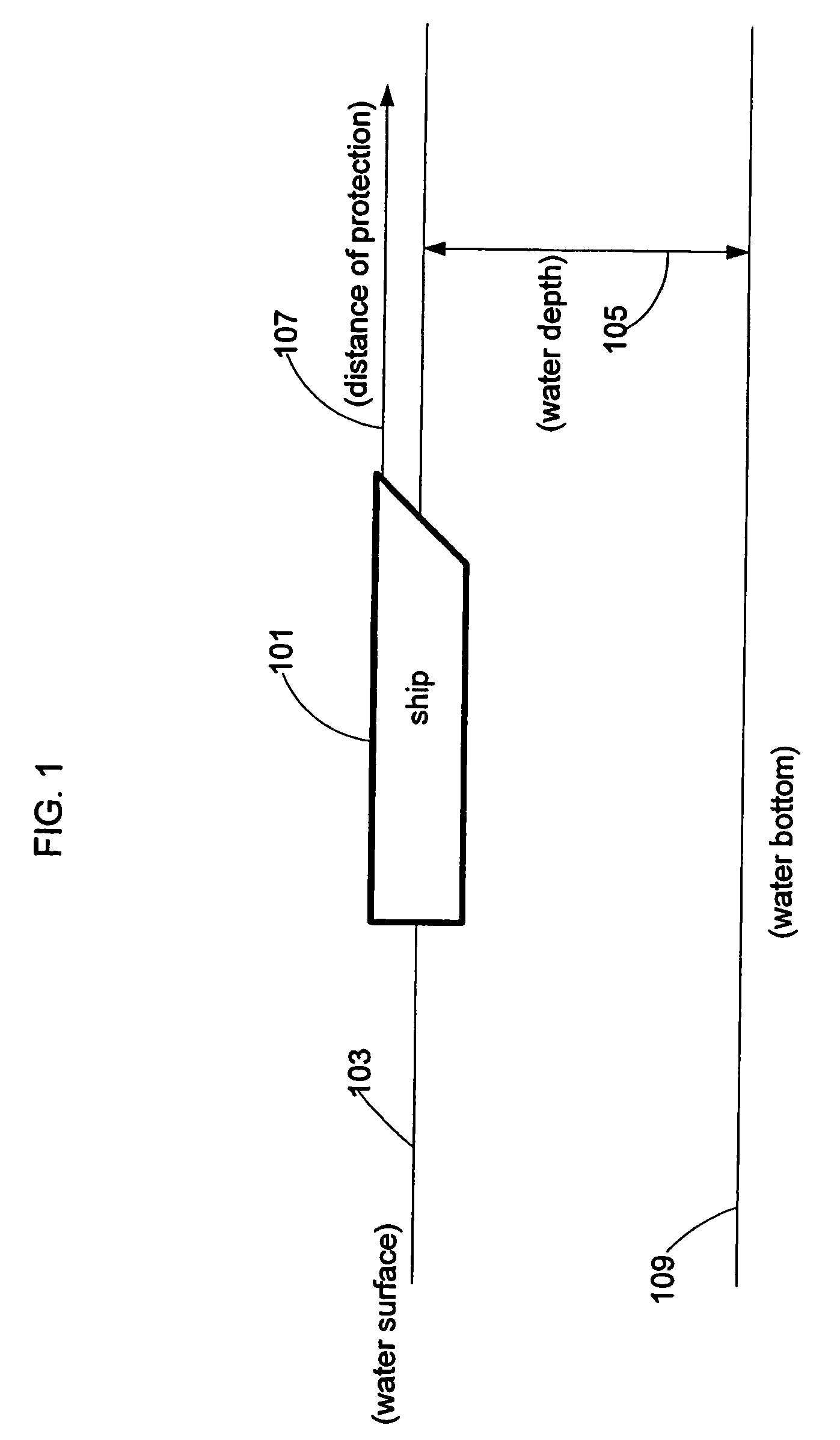
[0028]FIG. 1 illustrates a ship 101 that floats at a water surface 103 and that is protected by a sonar system. In FIG. 1, ship 101 is located in a harbor with a water depth 105. The sonar system protects ship 101 from intruders that pass under water (between water surface 103 and a water bottom 109) through a protection distance 107. Moreover, water depth 105 may vary in the protected region of ship 101.

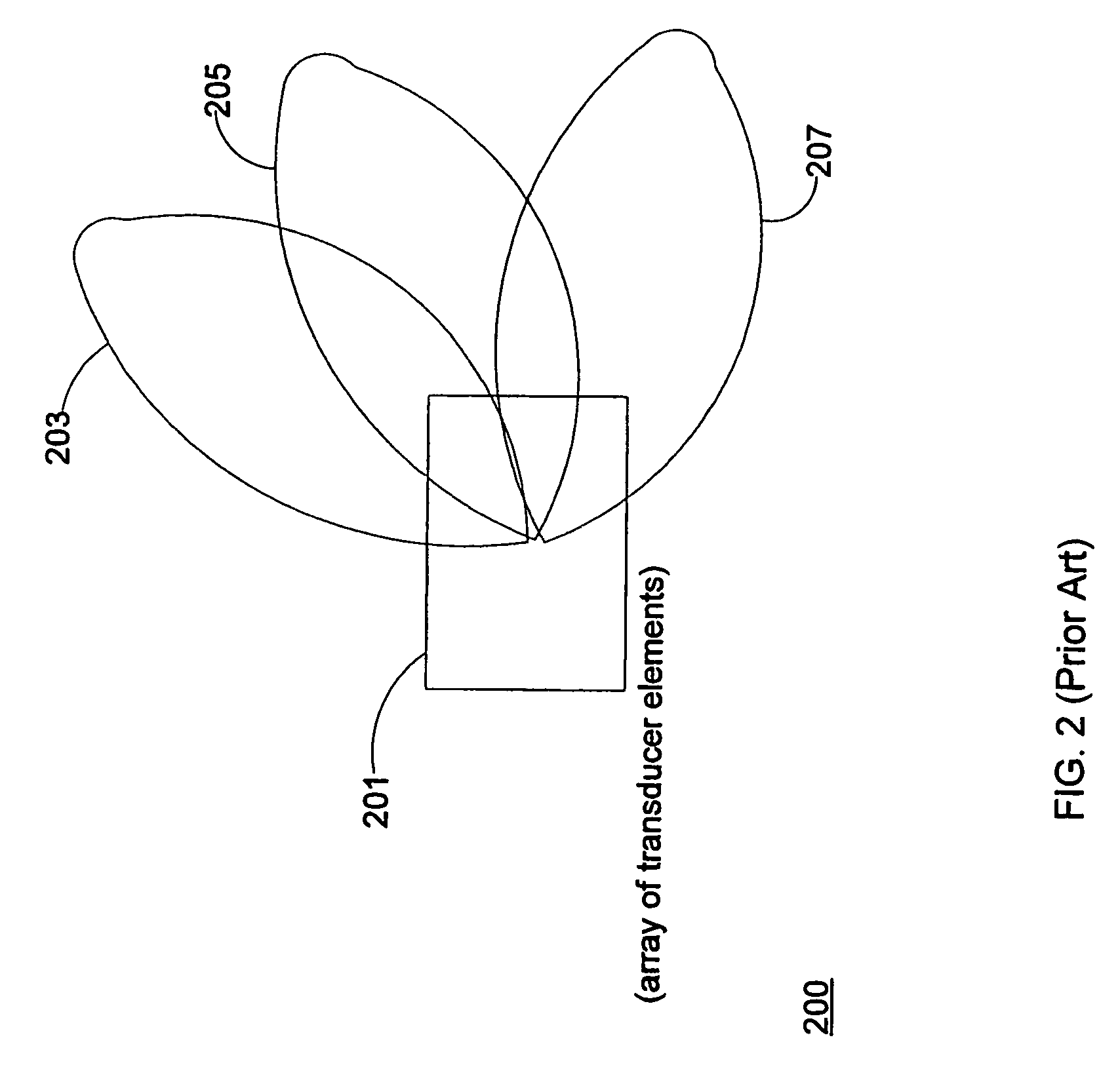
[0029]FIG. 2 shows a sonar system 200 that protects ship 101 from underwater intruders in accordance with prior art. Sonar system 200 deploys an array of transducer elemen...


PUM


Abstract

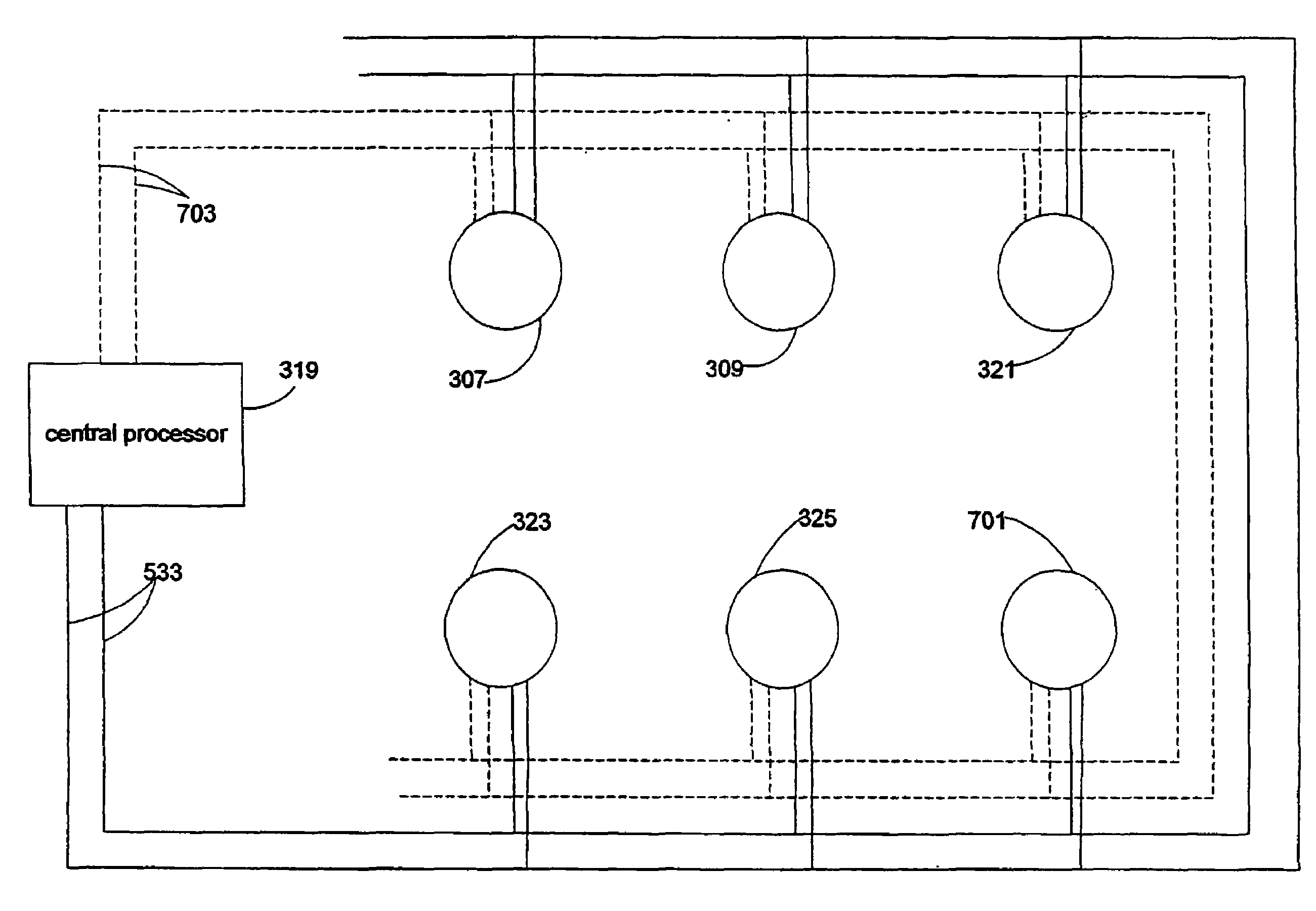
Methods and apparatus determine if an underwater intruder passes under a protective boundary. A sonar sensor system comprises a plurality of sonar sensor modules that are spaced on a protective boundary. A sonar sensor module comprises a sonar transducer (sonar array) that is characterized by an omni-directional radiation pattern that may overlap an omni-directional radiation pattern of an adjacent sonar sensor module transducer. The sonar sensor module collects sonar data such as range information of the target in relation to time. A central processor obtains the sonar data from each sonar module through a telemetry link. The central processor processes the sonar data from the plurality of sonar sensor modules in order to determine an estimated path of the target and may determine if the target should be considered as a threatening underwater intruder from a calculated threat level estimate based on this data.

Description

[0001]This application is a continuation-in-part of common-owned, U.S. application Ser. No. 10 / 346,414 filed on Jan. 17, 2003 now U.S. Pat. No. 6,813,220, naming Gary W. Hicks and Larry McDonald. The entire contents of which are incorporated herein by reference.[0002]The U.S. Government has a paid-up license in this invention and the right in limited circumstances to require the patent owner to license others on reasonable terms as provided for by the terms of N41756-02-C-4682 awarded by the U.S. Navy.FIELD OF THE INVENTION[0003]The present invention relates to an acoustic barrier to protect an asset such as a ship that abuts a body of water.BACKGROUND OF THE INVENTION[0004]Current world events highlight the need to protect both military and civilian ships that are situated in a harbor environment. Potential threats may originate at the surface of the water or below the surface of the water. In order to protect against underwater threats, a traditional diver sonar (SOund, NAvigation...

Claims


Application Information

Patent Timeline
Patent Type & Authority Patents(United States)
IPC IPC(8): H04B1/06H04B11/00G01S7/523G01S15/04G01S15/87
CPCG01S7/523G01S15/04G01S15/876
Inventor MCDONALD, LARRY R.HICKS, GARY W.
Owner SCI APPL INT CORP
Learn More