
ESD protection circuit between different voltage sources

a protection circuit and voltage source technology, applied in the direction of semiconductor devices, electrical apparatus, transistors, etc., can solve the problems of unable to effectively isolate two independent voltage sources from each other, the ability of the diode to drive current is not very good, and the leakage current of the diode is higher and the breakdown voltage is lower

Active Publication Date: 2007-07-17
REALTEK SEMICON CORP
View PDF13 Cites 18 Cited by
  • Summary
  • Abstract
  • Description
  • Claims
  • Application Information

AI Technical Summary

Benefits of technology

The invention provides an ESD protection circuit for an IC that uses different voltage sources. The circuit includes two sets of bipolar transistors, detection circuits, and a trigger circuit. The transistors are connected to voltage terminals and the detection circuits are connected to the bases of the transistors. The technical effect of this invention is to provide a reliable and effective protection against ESD damage in ICs that use different voltage sources.

Problems solved by technology

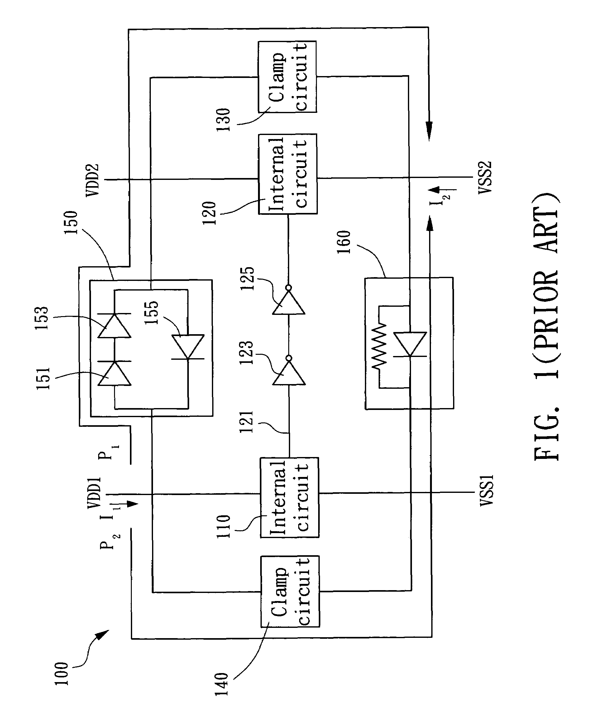
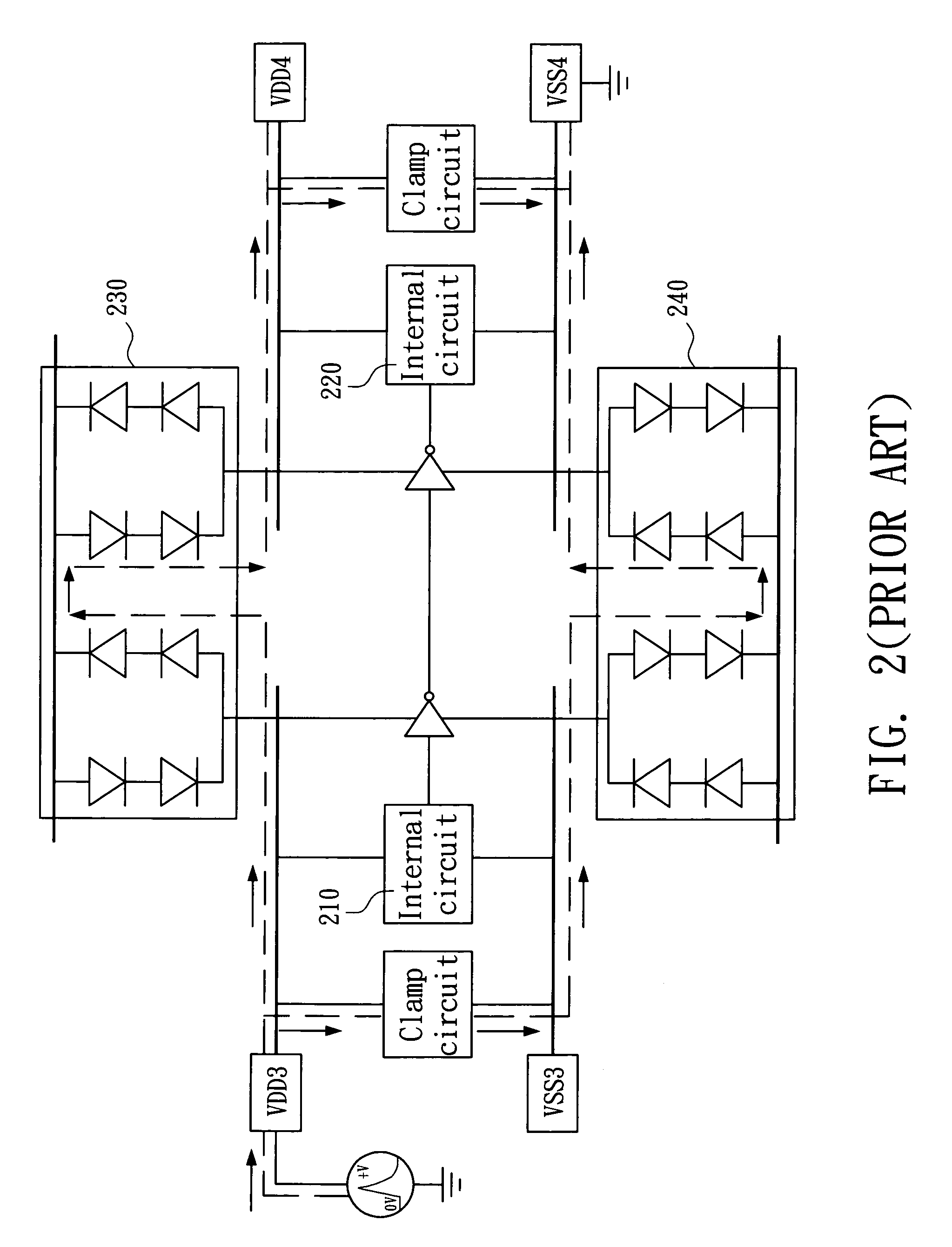
However, the diode of the conventional ESD protection circuit causes the following drawbacks.
1. The diode has a higher leakage current and a lower breakdown voltage, and cannot effective isolate two independent voltage sources from each other.
2. The capability of the diode for driving current is not very good, and thus the current caused by the ESD cannot be discharged quickly.

Method used


Image

  • ESD protection circuit between different voltage sources
  • ESD protection circuit between different voltage sources
  • ESD protection circuit between different voltage sources

Examples


Embodiment Construction

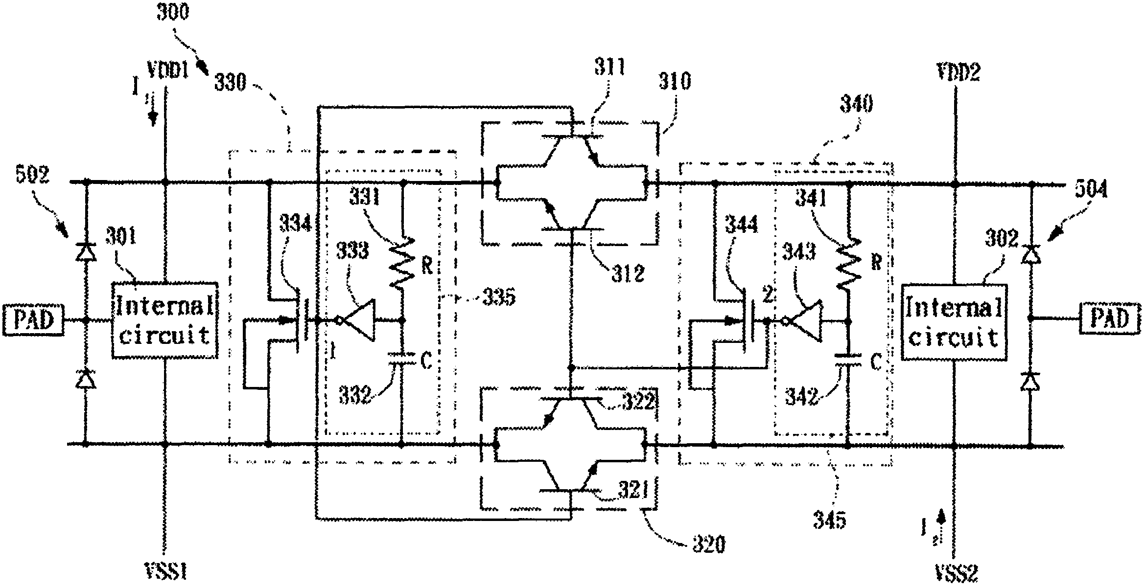
[0030]FIG. 3 is a schematic illustration showing an ESD protection circuit according to an embodiment of the invention. As shown in FIG. 3, the ESD protection mechanism in the integrated circuit 300 is implemented by using ESD detecting circuits 330 and 340 and ESD protection circuits 310 and 320, wherein the ESD detecting circuit 330 is coupled between power source terminals VDD1 and VSS1, the ESD detecting circuit 340 is coupled between power source terminals VDD2 and VSS2, the ESD protection circuit 310 is coupled between the VDD1 and the VDD2, and the ESD protection circuit 320 is coupled between the VSS1 and the VSS2. Besides, at least a first diode 502 (as shown in FIG. 5) may be connected between the VDD1 and the VSS1 for providing a discharging path from the VSS1 to the VDD1, and a second diode 504 (as shown in FIG. 5) may be connected between the VDD2 and the VSS2 for providing a discharging path from the VSS2 to the VDD2.

[0031]The ESD protection circuits 310 and 320 are im...


PUM


Abstract

An ESD protection circuit for hybrid voltage sources includes a first bipolar transistor set and a second bipolar transistor set, a first detection circuit, and a second detection circuit. The ON / OFF states of the first bipolar transistor set and the second bipolar transistor set are determined by the first and the second detection circuit, and the ON / OFF states function to isolate terminals of the different voltage sources and discharge electrostatic charges injected into one of the terminals.

Description

[0001]This application claims the benefit of Taiwan application Ser. No. 092128358, filed Oct. 14, 2003, the subject matter of which is incorporated herein by reference.BACKGROUND OF THE INVENTION[0002]1. Field of the Invention[0003]The invention relates to an ESD (Electrostatic Discharge) protection circuit, and more particularly to an ESD protection circuit for internal circuits using different voltage sources.[0004]2. Description of the Related Art[0005]An ESD (Electrostatic Discharge) protection circuit often applied in an integrated circuit. Owing to the large voltage of electrostatic charge, the integrated circuit must utilize the ESD protection circuit to prevent the electrostatic charge from damaging internal circuits of the integrated circuit.[0006]However, with the evolution of the technology, different voltage sources are used for the different internal circuits of the integrated circuit. Therefore, the ESD protection circuit is not only disposed between signal input and ...

Claims


Application Information

Patent Timeline
Patent Type & Authority Patents(United States)
IPC IPC(8): H02H9/00H01L29/70H01L21/33H01L21/822H01L27/02H01L27/04
CPCH01L27/0259H01L2924/0002H01L2924/00
Inventor YEH, TA-HSUNLIN, YUNG-HAOJEAN, YUH-SHENG
Owner REALTEK SEMICON CORP
Learn More