
Method for detecting transverse vibrations in an ultrasonic hand piece

Active Publication Date: 2007-07-17
ETHICON ENDO SURGERY INC
View PDF28 Cites 268 Cited by
  • Summary
  • Abstract
  • Description
  • Claims
  • Application Information

AI Technical Summary

Benefits of technology

[0022]In an alternative embodiment, a Multiple Level Drive Power vs. Power Delivered relationship and / or a Multiple Level Drive Power vs. Impedance relationship is used to detect or predict potential transverse mode problems, along with an “over-drive” of the hand piece at one or several power drive levels beyond the normal range of power levels used. These “over-drive” power levels are particularly effective at rapidly identifying problematic or potentially problematic transverse mode conditions.
[0027]The method provides an indication of whether a hand piece, which failed the power level tests, will exhibit transverse vibrational modes if it is used. In addition, the method eliminates the need to know the specific type of blade being used with the hand piece during diagnostic testing.

Problems solved by technology

These vibrations bend the blade, thereby causing the generation of heat, which drains energy from the desired longitudinal vibrations.

Method used


Image

  • Method for detecting transverse vibrations in an ultrasonic hand piece
  • Method for detecting transverse vibrations in an ultrasonic hand piece
  • Method for detecting transverse vibrations in an ultrasonic hand piece

Examples


Embodiment Construction

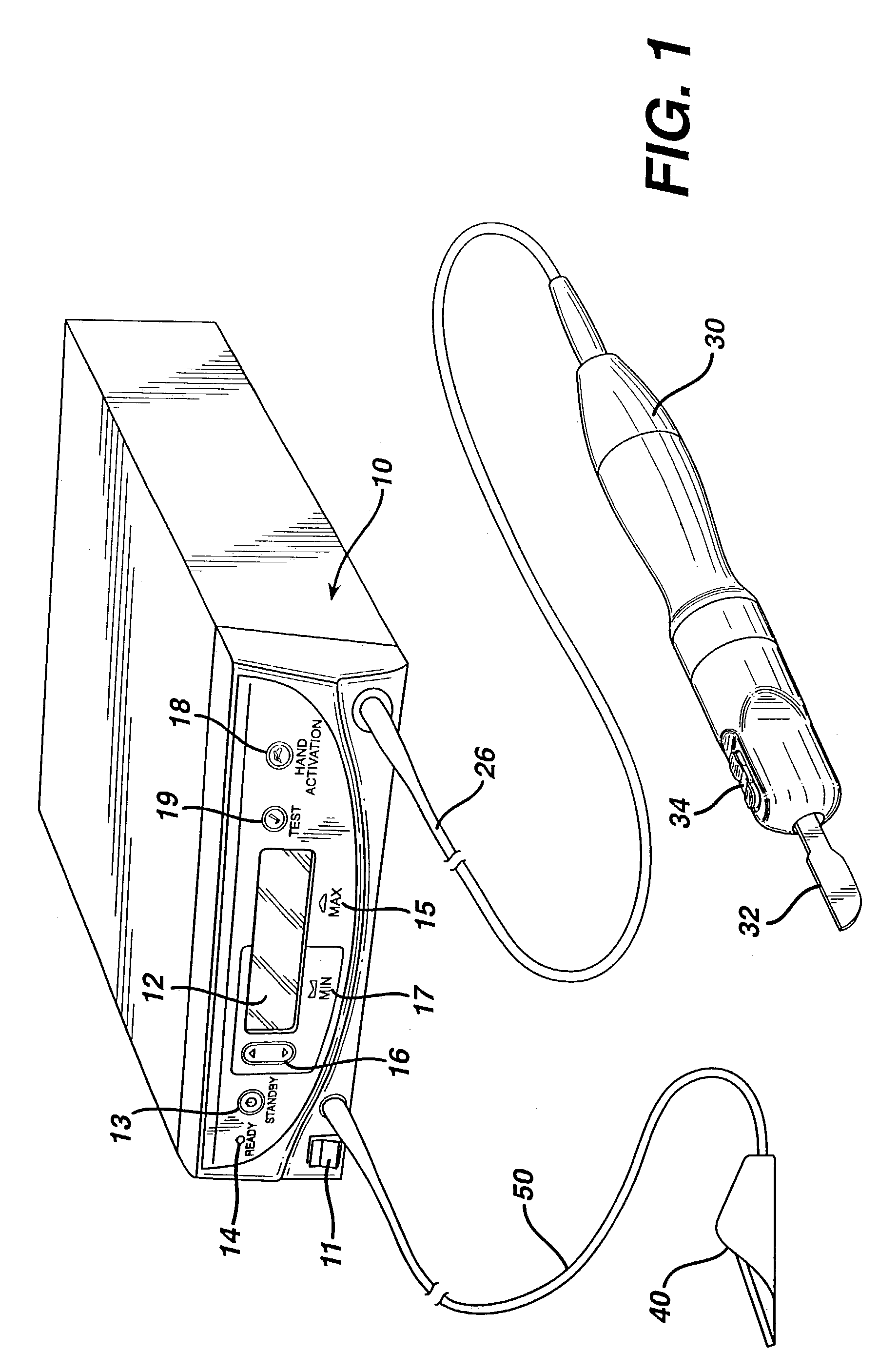
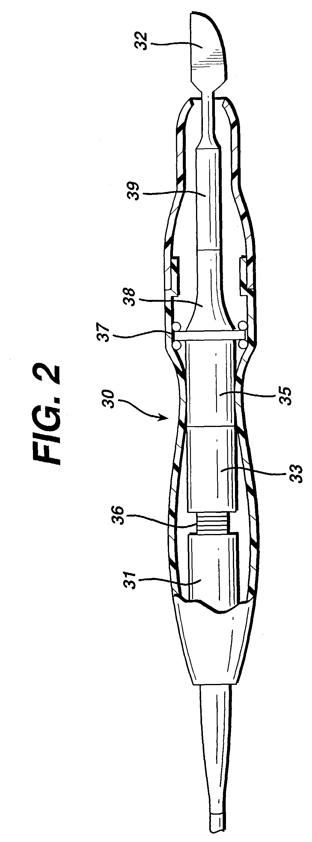
[0041]FIG. 1 is an illustration of a system for implementing the method in accordance with the invention. By means of a first set of wires in cable 20, electrical energy, i.e., drive current, is sent from the console 10 to a hand piece 30 where it imparts ultrasonic longitudinal movement to a surgical device, such as a sharp scalpel blade 32. This blade can be used for simultaneous dissection and cauterization of tissue. The supply of ultrasonic current to the hand piece 30 may be under the control of a switch 34 located on the hand piece, which is connected to the generator in console 10 via wires in cable 20. The generator may also be controlled by a foot switch 40, which is connected to the console 10 by another cable 50. Thus, in use a surgeon may apply an ultrasonic electrical signal to the hand piece, causing the blade to vibrate longitudinally at an ultrasonic frequency, by operating the switch 34 on the hand piece with his finger, or by operating the foot switch 40 with his ...


PUM


Abstract

A method for detecting transverse mode vibrations in an ultrasonic hand piece / blade is achieved by monitoring the power delivered to the hand piece / blade to determine whether it increases as expected when power levels applied to the hand piece / blade are changed. While the blade is being held in midair, the power delivered to the hand piece / blade and / or the impedance of the hand piece / blade is measured at a first power level. Using the value obtained at the first power level, the expected power at a second power level is calculated and used to set a pass / fail threshold level for an actual measured power. Alternatively, the threshold is set for the impedance is set. Next, the actual power delivered to the hand piece / blade and / or the impedance of the hand piece / blade is measured at a level 5 power setting. A determination is made whether the hand piece / blade exhibits transverse mode behavior based on whether the actual measured power exceeds the established pass / fail threshold level. If this is the case, operation of the generator is inhibited, a “Transverse Mode Vibrations Present in Hand Piece / Blade” error code is stored in the generator, and a “Bad Hand Piece” message is displayed on a liquid crystal display on the generator. In addition, a method for detecting transverse mode vibration in an ultrasonic hand piece / blade is achieved by monitoring power delivered to the hand piece / blade to determine if the an extraordinary power increase occurs as the drive frequency is shifted downward and / or upward from a primary intended resonance operating frequency.

Description

RELATED APPLICATIONS[0001]The present invention relates to, and claims priority of, U.S. Provisional Patent Application Ser. No. 60 / 242,251 filed on Oct. 20, 2000. This is a division, of application Ser. No. 09 / 953,006, filed Sep. 14, 2001 now U.S. Pat. No. 6,679,899. Each of these prior applications is hereby incorporated herein by reference, in its entirety.BACKGROUND OF THE INVENTION[0002]1. Field of the Invention[0003]The invention generally relates to ultrasonic surgical systems and, more particularly, to a method for detecting transverse mode vibrations in an ultrasonic hand piece / blade.[0004]2. Description of the Related Art[0005]It is known that electric scalpels and lasers can be used as a surgical instrument to perform the dual function of simultaneously effecting the incision and hemostatis of soft tissue by cauterizing tissues and blood vessels. However, such instruments employ very high temperatures to achieve coagulation, causing vaporization and fumes as well as splat...

Claims


Application Information

Patent Timeline
IPC IPC(8): A61B17/32A61B17/00
CPCA61B17/320068A61B2017/00026A61B2017/0003A61B2017/00119A61B2017/00137A61B2017/320069A61B2017/320071A61B2017/320089
Inventor WIENER, EITAN T.DONOFRIO, WILLIAM T.
Owner ETHICON ENDO SURGERY INC
Learn More