
Light-generating apparatus having a reflector

a light-generating apparatus and reflector technology, applied in lighting and heating apparatus, lighting heating/cooling arrangements, coatings, etc., can solve the problems of large thermal component loss of such light sources, the inability of light-generating systems or apparatuses to arbitrarily small configurations, and the compounding of problems, so as to improve the dissipation of heat, improve the cooling power, and improve the effect of thermal power distribution

Inactive Publication Date: 2007-07-17
AUER LIGHTING
View PDF36 Cites 19 Cited by
  • Summary
  • Abstract
  • Description
  • Claims
  • Application Information

AI Technical Summary

Benefits of technology

"The invention is a light-generating system that includes a reflector and a device for improving the dissipation of heat. The device for improving heat dissipation can be connected to the reflector or placed on the outside of the reflector. It can be a radiation-absorbing surface or a coating that absorbs thermal radiation. The system can also have air cooling to absorb heat from the components of the device. The invention provides a solution to improve the cooling of the reflector and other components of the light-generating apparatus."

Problems solved by technology

However, a large thermal component is lost with such light sources.
Because of the thermal power that occurs, the light-generating systems or apparatuses cannot be of arbitrarily small configuration in order not to permit the thermal input per unit of area of the reflector to become too high.
This problem is also compounded, in particular, in the case of cold-light reflectors, for which longer wave radiation components are not reflected but pass through the reflector.
Further problems arise owing to the large change in temperature occurring during switching on and off.

Method used


Image

  • Light-generating apparatus having a reflector
  • Light-generating apparatus having a reflector
  • Light-generating apparatus having a reflector

Examples


Embodiment Construction

[0041]FIG. 1 depicts a cross sectional illustration through an embodiment of an inventive light-generating apparatus that is denoted as a whole by the reference numeral 1.

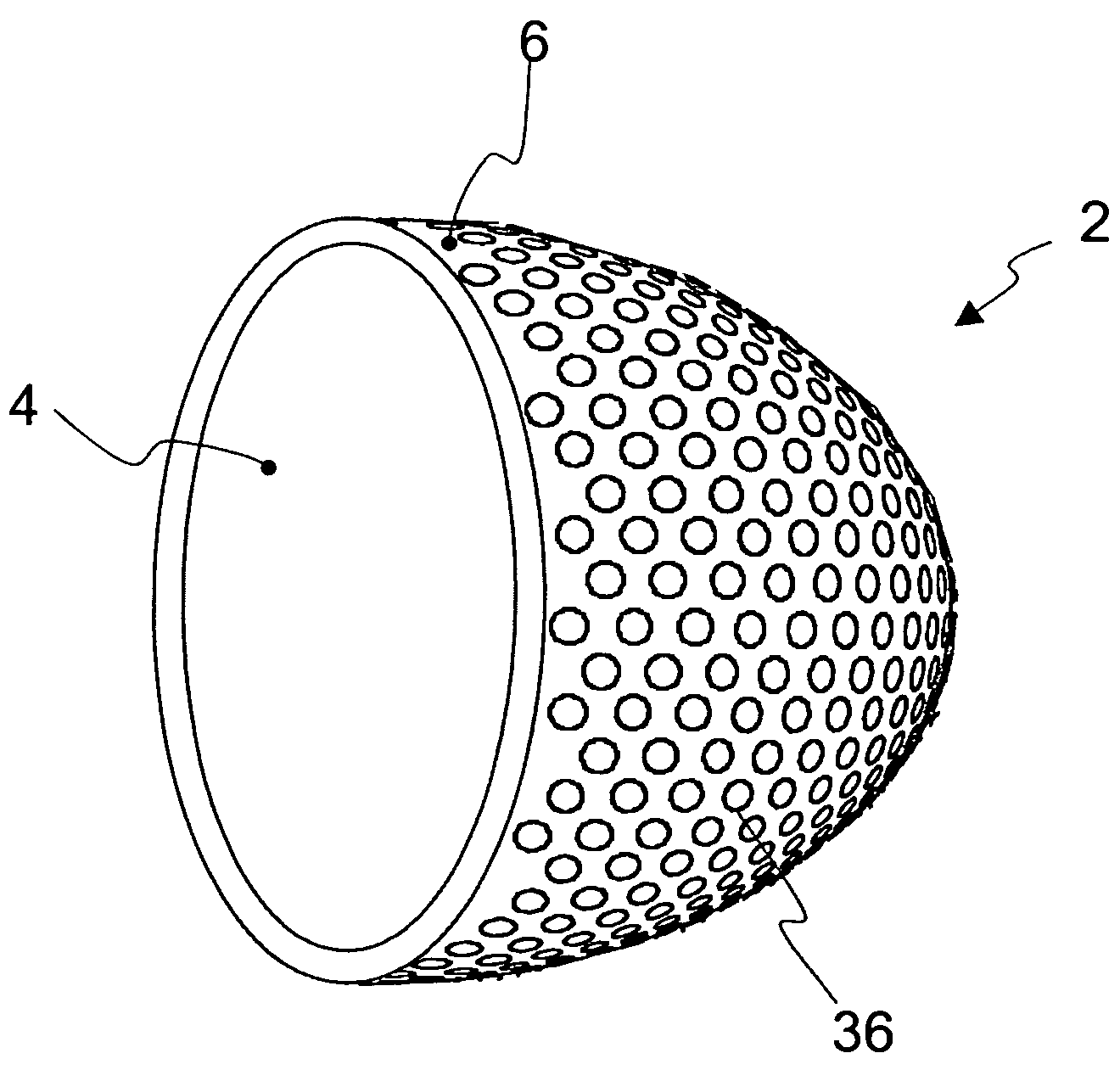
[0042]The light-generating apparatus 1 comprises a reflector 2 with an inside 4 and an outside 6, as well as a device for improving the dissipation of heat from the reflector 2. The inside 4 is concavely curved so that light from a luminous means that is arranged in or in front of the cavity defined by the curve inside is focused by reflection from the surface of the inside 4.

[0043]The reflector can be produced from metal, glass, glass ceramic or plastic, or can comprise a composite material made from two or more of these materials. The plastics of polycarbonate, polyetherimide, polymethyl methacrylate, cyclic olefin, olefin copolymer, or polyether sulfone, in particular, can be used as material for a plastic reflector or a reflector having a composite reflector body. The reflector 2 of the embodiment shown in FIG....


PUM

PropertyMeasurementUnit
heataaaaaaaaaa
shapeaaaaaaaaaa
resilientaaaaaaaaaa

Abstract

The invention envisages a light-generating apparatus that provides effective cooling of the reflector, the apparatus comprising a reflector and a device for improving the dissipation of heat from the reflector.

Description

BACKGROUND OF THE INVENTION[0001]1. Field of the Invention[0002]The invention relates in general to illuminating means, in particular the invention relates to a light-generating apparatus having a reflector and a cooling structure.[0003]2. Description of Related Art[0004]Attempts are being made, for example in the field of projection technology, to reduce the size of light-generating systems in conjunction with identical or increased power. This is desirable, inter alia, in order to achieve an increased brilliancy. Even today, use is still being made for projectors of predominantly conventional luminous means which operate, for example, with incandescent wires, or particularly with electric arcs. As high-brilliancy sources, these light sources are distinguished from lasers, in particular, by the high light power and the realistic color temperature and a high spectral blue component.[0005]However, a large thermal component is lost with such light sources. Because of the thermal power...

Claims


Application Information

Patent Timeline
Patent Type & Authority Patents(United States)
IPC IPC(8): F21V7/20F21V29/00F21V7/22F21V29/02F21V29/505F21Y101/00
CPCF21V7/22F21V29/505F21V29/02F21V7/24F21V7/28F21V29/60F21V29/70F21V29/74F21V29/83F21V31/03
Inventor BEWIG, LARSZIERFAS, ULRICHHOLDMANN, TORSTEN
Owner AUER LIGHTING
Learn More