
Wellbore operations monitoring and control systems and methods

a wellbore operation and monitoring system technology, applied in the direction of borehole/well accessories, survey, drilling pipes, etc., can solve the problems of undifferentiated mechanical specific energy, system and method use, ambiguous and/or inconsistent determination of mechanical specific energy, etc., to improve the diagnostic potential and efficiency of bit diagnosis, and more accurate calculations

Active Publication Date: 2007-07-17
VARCO I P INC
View PDF10 Cites 107 Cited by
  • Summary
  • Abstract
  • Description
  • Claims
  • Application Information

AI Technical Summary

Benefits of technology

"The present invention provides methods for using sensor data to calculate mechanical specific energy values for a wellbore system, including the bit, drill string, and other components. These values can be used to optimize wellbore operations, improve energy efficiency, and identify the source of energy loss. The invention also provides systems for monitoring and analyzing the energy loss in real-time, allowing for real-time confirmation that the chosen solutions are not negatively impacting other components of the drilling system. The invention uses a combination of surface and downhole data to determine the mechanical specific energy of each part of the wellbore system. Overall, the invention enhances the diagnostic potential and efficiency of diagnosing bit and drill string mechanics, provides more understandable data interpretation, and improves the accuracy of calculations."

Problems solved by technology

The process worked in water-based drilling fluids that had replaced earlier synthetic muds because both balled-new bits and dull bits exhibit similar levels of inefficiency.
In general, many prior art systems and methods use undifferentiated mechanical specific energy, i.e., calculations of mechanical specific energy based on sensed and measured values without taking into account the location of the sensors and measurement apparatuses that produce them.
The use of such undifferentiated measurements or parameters such as torque, rotational speed, etc. can lead to ambiguous and / or inconsistent determinations of mechanical specific energy.

Method used


Image

  • Wellbore operations monitoring and control systems and methods
  • Wellbore operations monitoring and control systems and methods
  • Wellbore operations monitoring and control systems and methods

Examples


Embodiment Construction

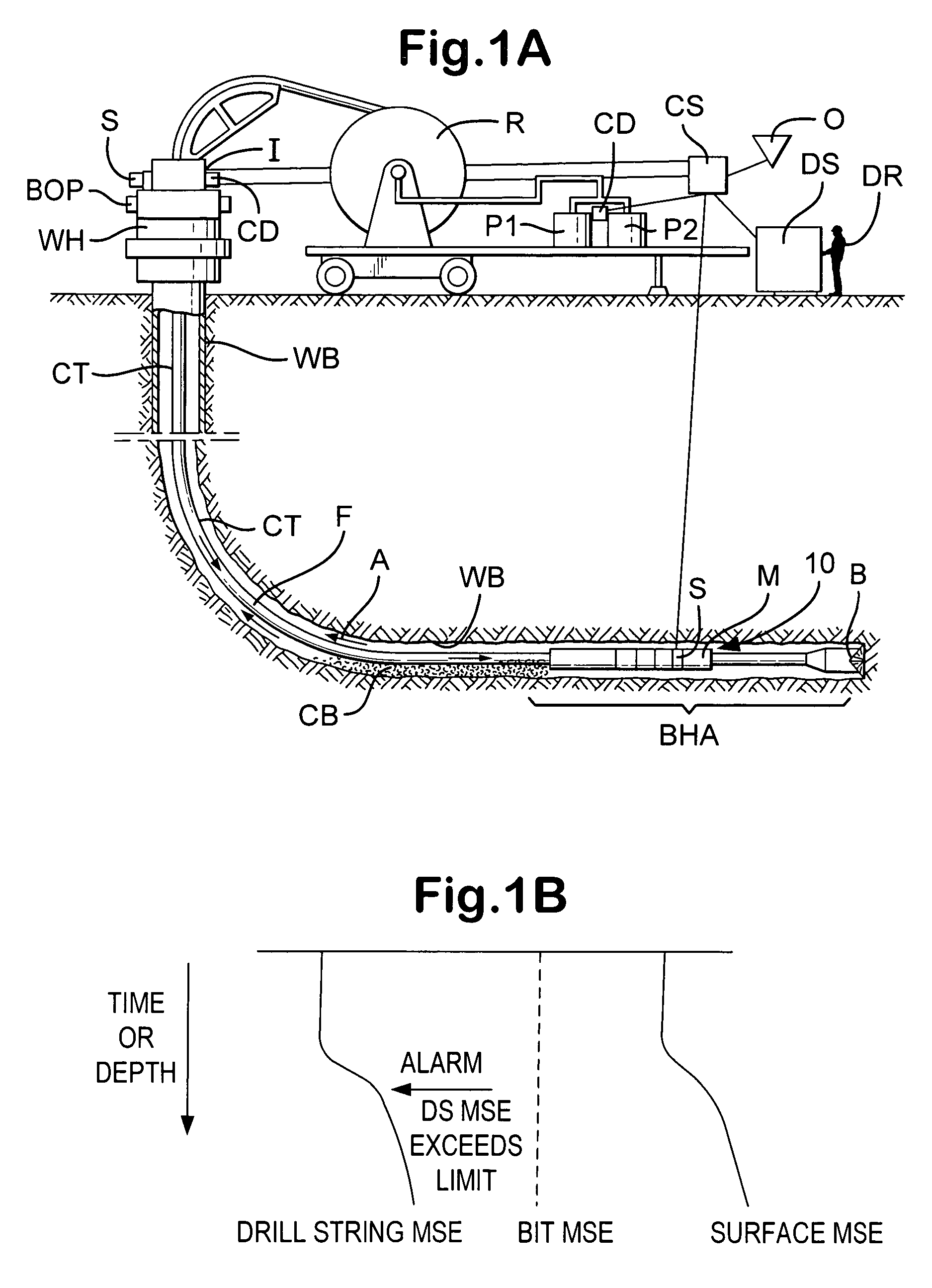
[0041]In one particular embodiment of a system and method according to the present invention, as shown in FIG. 1A, a downhole motor drilling system 10 is used to drill a wellbore WB. The system 10 has a bottom hole assembly BHA with a bit B and a mud motor M which is connected to coiled tubing CT from a reel R which extends through an injector I into and through a BOP and a wellhead WH. Fluid F is pumped down to the BHA by pumps P1, P2. Cuttings CB flow up an annulus A with fluid F pumped out of the bit B. Sensors S provide signals indicative of various parameters, including, e.g., WOB, ROP, torque, bit rotation speed, and bit cross-section area. WOB, ROP, and / or torque can be measured by sensor(s) S at the injector I and / or downhole. Bit rotational speed (zero at the surface, by definition) is measured downhole. The sensors are in communication with a system CS (e.g. a computer system or systems, PLC's, and / or DSP's). The system CS calculates differentiated mechanical specific ener...


PUM


Abstract

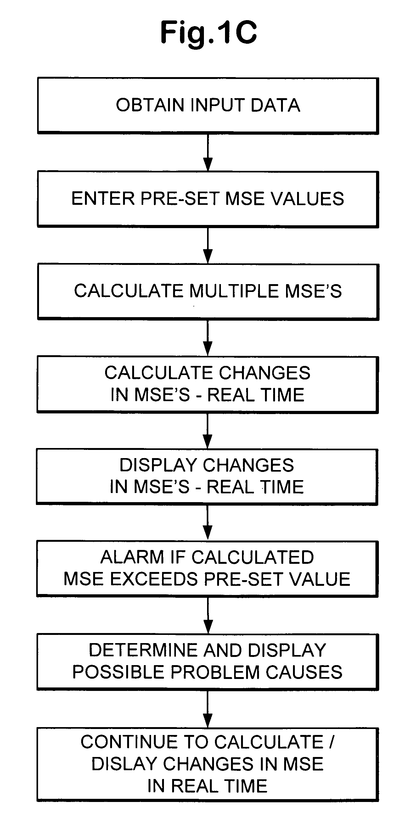
A method for a wellbore operation with a wellbore system, the method, in at least certain aspects, including acquiring with sensor systems data corresponding to a plurality of parameters, the data indicative of values for each parameter, each parameter associated with part of the wellbore system, and, based on said data, calculating a value for each of a plurality of mechanical specific energies each related to a mechanical specific energy for a part of the wellbore system; and, in some aspects, monitoring in real time the value of each of the mechanical specific energies; and, in certain aspects, using such determined values to alter, change, improve, or optimize operations.

Description

BACKGROUND OF THE INVENTION[0001]1. Field of the Invention[0002]The present invention is directed to monitoring and controlling wellbore operations, and, in one particular aspect, to monitoring and controlling wellbore drilling operations in real time.[0003]2. Description of Related Art[0004]The prior art discloses a wide variety of systems and methods for monitoring wellbore operations and for sensing and measuring parameters related to such operations, both downhole and at the surface. The prior art also discloses a wide variety of sensors, measurement apparatuses, devices, and equipment for sensing, measuring, recording, displaying, calculating, processing, and transmitting measured values for operational parameters, including, but not limited to, weight on bit (WOB), rate of penetration (ROP), rotary speed, bit speed, top drive speed, downhole motor speed, and torque on a drillstring or on a bit.[0005]Many systems and methods have been proposed and implemented for using such sen...

Claims


Application Information

Patent Timeline
Patent Type & Authority Patents(United States)
IPC IPC(8): E21B47/12
CPCE21B45/00E21B49/003
Inventor KOEDERITZ, WILLIAM LEOTARVIN, TERRY LYNN
Owner VARCO I P INC
Learn More