
Cleaning unit for optical connector and cleaning tool for optical connector

a cleaning unit and optical connector technology, applied in the direction of carpet cleaners, instruments, photosensitive materials, etc., can solve the problems of increasing transmission loss, difficult to confirm whether the cleaning tool is working, and cleaning may not always be successful, so as to achieve the effect of convenient cleaning

Inactive Publication Date: 2007-07-17
THE FUJIKURA CABLE WORKS LTD
View PDF9 Cites 15 Cited by
  • Summary
  • Abstract
  • Description
  • Claims
  • Application Information

AI Technical Summary

Benefits of technology

[0011]Therefore, it is an object of the present invention to provide a cleaning unit and cleaning tool for optical connector which can easily and reliably clean the join end faces of optical connectors while they are inserted inside a connector housing.
[0013]According to the optical connector cleaning unit, the cleaning member is driven by a drive mechanism, thereby making it easier to wipe clean the join end face of the optical connector.
[0014]Furthermore, the operation of wiping clean the join end face of the optical connector is made even easier by using the moving force of the drive auxiliary mechanism to drive the cleaning member.
[0016]According to the above optical connector cleaning unit, the cleaning member is accurately touched the join end face of the optical connector inside the connector housing merely by inserting the insertion section into the connector housing. At the time of inserting the cleaning member into the connector housing, the cleaning member is prevented from touching the inner walls of the connector housing. Therefore, the cleaning member is prevented from contaminating. Moreover, when the join end face is wiped clean by operating the cleaning member, the cleaning member is easily maintained in an appropriate position where the cleaning member is touched against the join end face, enabling the join end face to be cleaned more reliably and easily. Even if the cleaning tool is held manually, the cleaning member is unlikely to suffer positional deviation resulting from movement of the hands. Since the insertion section can be supported inside the connector housing with a very light force, workability is good.
[0018]According to the above optical connector cleaning tool, since the cleaning member can be driven by the moving force from the drive auxiliary mechanism, it becomes easier to wipe clean the join end face of the optical connector. By disconnecting the connection section and replacing the optical connector cleaning unit, the cleaning member can easily be replaced.
[0020]According to the above optical connector cleaning tool, cleaning can be performed easily even if the optical connector and the connector housing are located in comparatively narrow, high, or low places.

Problems solved by technology

If there is fouling or dust, or spot such as oil on the join end faces of the optical connectors at the time of inserting the optical connectors into the connector housing and connecting them together, this may lead to problems such as causing damage when they are inserted and removed or increasing the transmission loss; for this reason, the join end faces must be cleaned prior to connection.
Since the join end face of the optical connector to be cleaned is placed at the far end from the connector insertion hole, it is extremely hard to see, making it difficult to confirm whether the cleaning tool is properly touching the join end face and how the cleaning operation is proceeding; consequently, the cleaning may not always be successful.
Furthermore, when the cleaning tool touches the side walls of the connector housing during the cleaning operation, the cleaning tool becomes dirty, and may damage or soil the join end face if the cleaning tool directly touches the join end face in this state; for this reason, the cleaning tool must be inserted with great care, making the operation troublesome.
However, the operation of inserting the optical connectors into the connector housing after cleaning must be performed with great care to ensure that fouling, dust, and the like, do not adhere to the optical connectors; this, combined with the time taken to insert and remove the optical connectors, makes the operation considerably more complex.

Method used


Image

  • Cleaning unit for optical connector and cleaning tool for optical connector
  • Cleaning unit for optical connector and cleaning tool for optical connector
  • Cleaning unit for optical connector and cleaning tool for optical connector

Examples


second embodiment

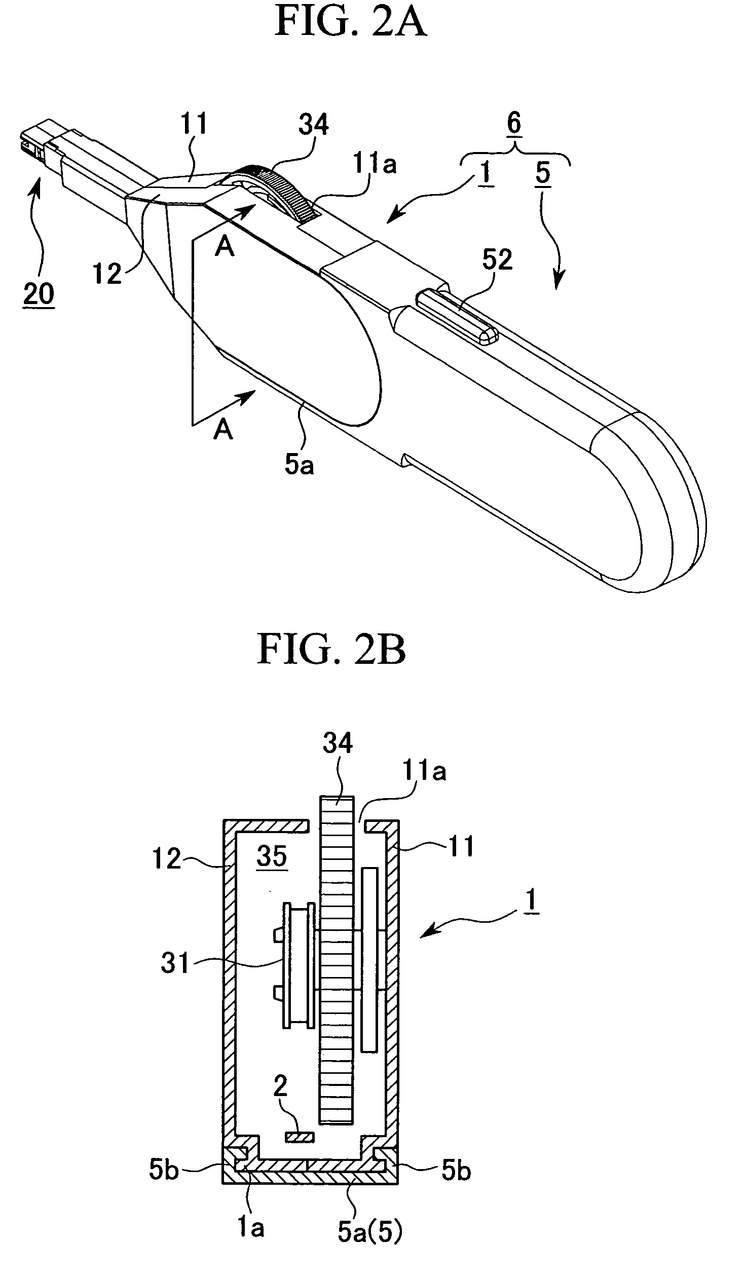
[0073]Drive auxiliary unit 5 comprises a drive auxiliary mechanism 50 which applies a driving force to tape feeding mechanism 3. One example of the specific constitution of drive auxiliary mechanism 50 would be that incorporated in a drive auxiliary unit 205, described later in a

[0074]As shown in FIGS. 3A and 3B, connection section 4 is, in detail, composed of a gear 44, which is supported by a shaft 44a, belt wheels 41 and 42, which are attached around the outer peripheries of take-up reel supporting shaft 33 and shaft 44a, and a belt 43, which is wound around belt wheels 41 and 42. When gear 44 rotates, its rotational force is transmitted by the rotation of belt wheels 41 and 42 via belt 43 to take-up reel supporting shaft 33, thereby driving tape feeding mechanism 3.

[0075]As shown in FIGS. 3 and 4, an opening 46 is provided in the rear edge section of unit main body 10. Opening 46 is closed by engaging a clipping projection 45a of a lid 45 to an edge 46a of opening 46.

[0076]With ...

first embodiment

[0103]Connection section 204 comprises a gear 291, attached to the outer periphery of take-up reel supporting shaft 33, and a gear 292, attached to the outer periphery of a shaft 293, which is connected to case half-body 11. Gears 291 and 292 are meshed. As in the first embodiment, when cleaning unit 201 and drive auxiliary unit 205 are connected together and a gear 245 (see FIG. 12) of drive auxiliary unit 205 meshes with gear 292, gear 292 is driven by drive auxiliary unit 205, the rotational force of gear 292 being transmitted via gear 291 to take-up reel supporting shaft 33, tape feeding mechanism 3.

[0104]In cleaning unit 201, a section 19 of unit main body 10 which is near insertion section 20 is narrow, and has a protruding wall 19a for reinforcing a narrow section 19. Protruding wall 19a restricts the movement of the fouling on cleaning tape 2 by separating the path of cleaning tape 2 to be clean, which travels from supply reel 30 toward head member 23, from the path of clean...

case 210

[0106]Case 210 has a two-part structure comprising first and second case half-bodies 211 and 212, which are made of plastic or the like; case 210 can be arranged into a single piece by facing case half-bodies 211 and 212 toward each other, fitting their peripheral edges together, and, for example, screwing them with screws 213 and 214.

[0107]An open section 266 is provided at the front edge side of case 210 (the left side of FIG. 13) for exposing some of the teeth of a gear 245 of drive auxiliary mechanism 207 to the outside of case 210.

[0108]Notches 221a and 212a are provided in the top of case half-bodies 211 and 212, and function as a window 210a for exposing a control switch 250 (explained later) to the outside of case 210 when case 210 is assembled.

[0109]Connection mechanism 208 has a pair of pressing members comprising a plate spring 262 on the top of the front end of case 210, and a lever-like clipping member 264 which faces plate spring 262 at the bottom of the front end of c...


PUM


Abstract

A join end face of an optical connector is easily and reliably cleaned when the optical connector has been inserted into a connector housing, by using an optical connector cleaning unit comprising a cleaning member which wipes clean a join end face of an optical connector inside a connector housing by relative motion against the join end face, a drive mechanism which drives the cleaning member, and a connection section which enables a drive auxiliary mechanism for applying a moving force to the drive mechanism to be connected, and an optical connector cleaning tool in which a drive auxiliary unit comprising the drive auxiliary mechanism has been connected to the connection section of the optical connector cleaning unit.

Description

BACKGROUND OF THE INVENTION[0001]1. Field of the Invention[0002]The present invention relates to a cleaning unit for optical connector and a cleaning tool for optical connector, which clean the joint side face of an optical connector in a connector housing.[0003]2. Description of Related Art[0004]As is widely known, in a plug-adaptor-plug connection type optical connector, optical connectors (plugs) are inserted into a connector housing to be an adaptor from opposite sides of the adaptor, and are connected inside the adaptor.[0005]In a plug-receptacle connection type optical connector, one optical connector (a ferrule or the like) to be connected is held inside a connector housing to be a receptacle at one side thereof, and the other optical connector (plug) is inserted into the receptacle from the other side of the receptacle and connected to the one optical connector.[0006]To connect optical connectors inside a connector housing such as an adaptor or a receptacle, the side faces o...

Claims


Application Information

Patent Timeline
IPC IPC(8): B08B1/00G02B6/36B08B11/00
CPCB08B1/008B08B11/00G02B6/3866B08B1/30
Inventor FUJIWARA, KUNIHIKOISHIKAWA, TAKAAKITANAKA, YUWA
Owner THE FUJIKURA CABLE WORKS LTD
Learn More