
Method of determining transmit power for transmit eigenbeams in a multiple-input multiple-output communications system

a communication system and transmit power technology, applied in diversity/multi-antenna systems, power management, wireless communication, etc., can solve the problems of adversely affecting any one or all of the parameters of a signal, the quality of communication channels can greatly affect the throughput of the communication system, and the information being carried by said signals to be received erroneously

Inactive Publication Date: 2007-07-10
WSOU INVESTMENTS LLC
View PDF3 Cites 43 Cited by
  • Summary
  • Abstract
  • Description
  • Claims
  • Application Information

AI Technical Summary

Benefits of technology

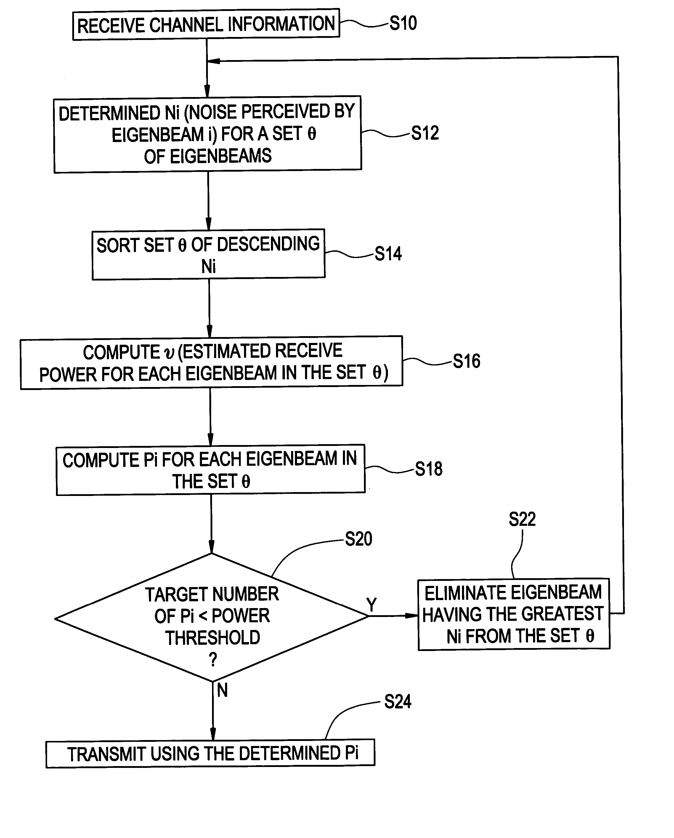
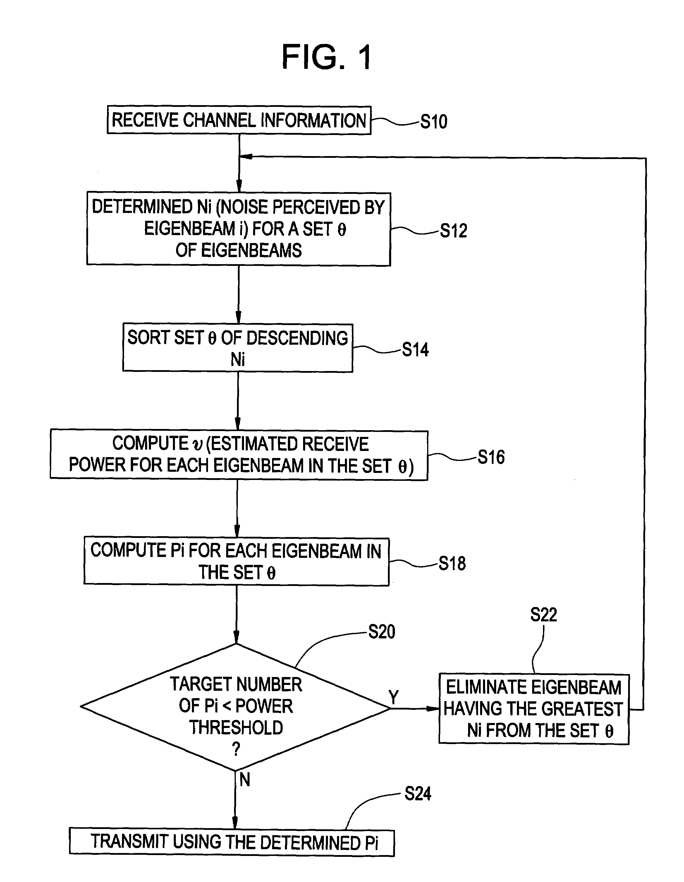
[0018]As an additional aspect of this exemplary embodiment, the set of eigenbeams may be modified to remove at least one eigenbeam when the determined transmit power for a desired number of eigenbeams is less than a power threshold.
[0019]Additionally, according to the present invention, the dete...

Problems solved by technology

As the communication signals propagate through the air, they are adversely affected by various anomalies that distort such signals and cause part or all of the information being carried by said signals to be received erroneously.
The quality of the communication channels can greatly affect the communication system's throughput.
The various anomalies of a communication channel can adversely affect any one or all of a signal's parameters; some of these parameters include signal amplitude, signal phase, signal frequency.
These brute force methods require a relatively large amount of information to be fed back to the transmit antennas.
Many communication systems have limited bandwidth for their signaling channels through which other critical information are conveyed.
It may not, therefore, be practical to send all of the feedback information.
Also, because the communication channel is a continually varying dynamic system, it may not be possible to efficiently and quickly modify the transmit signal to reduce its vulnerability to the channel anomalies.
Further, many times some of the channel information being transmitted in the form of eigenvalues and / or eigenvectors are not as accurate in their characterization of the communication channel.
However, for a multiple-transmit-multiple-receive antenna system, this method will not work simply because the channels between different antennas are interfering with each other.
Artificial ways of providing different transmit power to different eigenbeams is possible but this involves experimental fine tuning to determined the amount of power should be given and is usually not very effective.

Method used


Image

  • Method of determining transmit power for transmit eigenbeams in a multiple-input multiple-output communications system
  • Method of determining transmit power for transmit eigenbeams in a multiple-input multiple-output communications system
  • Method of determining transmit power for transmit eigenbeams in a multiple-input multiple-output communications system

Examples


Embodiment Construction

[0023]The present invention provides a method of improving the determination of the transmit power of each eigenbeam transmitted by over transmit antennas of a multiple-input multiple-output communication system. To better understand the method of the present invention, some of the eigenbeam forming information discussed in the background will be repeated, albeit in a way suited for better comprehending the present invention. Then some of the mathematical concepts used in deriving the present invention will be explained. Finally, an embodiment of the method of the present invention will be explained with reference to the flow chart illustrated in FIG. 1.

Some Preliminary Comments on M×N Eigen Beam Forming Systems

As discussed in the background of the invention section, in a M×N (M transmit antenna, N receive antenna) Multi-Input, Multi-Output (MIMO) system, the received flat fading channel at the receiver can be written as:

[0024]H=[h11h21⋯hM1h12h22⋯hM2⋮⋮⋰⋮h1⁢Nh2⁢N⋯hMN](1)

where hÿs′ ar...


PUM


Abstract

In the method according to the present invention, a transmit power for each eigenbeam in a set of eigenbeams forming at least a portion of a multiple transmit antenna system is determined based on noise associated with each eigenbeam in the set of eigenbeams. The set of eigenbeams is for transmitting a number of parallel complex Gaussian channels.

Description

BACKGROUND OF THE INVENTION[0001]Antennas are part of some of the more critical components of a communication system, and in particular, wireless communication systems. In wireless communication systems, communication signals that are transmitted by antennas over traffic channels and signaling channels will at some point propagate through the air and be received by other antennas. Thus, part of or all of the medium of the traffic and signaling channels is the air itself. The traffic channels are communication channels through which users of the wireless communication system convey (i.e., transmit and / or receive) communication signals to each other. The communication signals typically carry information being conveyed between users. The signaling channels are communication channels through which signals that facilitate the control, maintenance and management of the communication system are conveyed. The signaling signals are typically transmitted by system equipment and user equipment...

Claims


Application Information

Patent Timeline
IPC IPC(8): H04L27/04H04B7/00H04B7/005H04B7/04
CPCH04B7/0408H04B7/0417H04B7/0632H04W52/42H04B7/0443H04W52/26H04W52/34
Inventor LIU, JUNG-TAOLIU, YOUJIANRUDRAPATNA, ASHOK
Owner WSOU INVESTMENTS LLC
Learn More