
Time-lapse seismic survey of a reservoir region

a reservoir region and time-lapse seismic technology, applied in the field of method of investigating a reservoir region, can solve the problems of a large thickness of the reservoir region or layer, and a large amount of seismic data processing in the reservoir region

Active Publication Date: 2007-07-10
SHELL USA INC
View PDF17 Cites 48 Cited by
  • Summary
  • Abstract
  • Description
  • Claims
  • Application Information

AI Technical Summary

Benefits of technology

The present invention provides a method for studying a reservoir region in a subsurface formation using a time-lapse seismic survey. This method involves analyzing the changes in a seismic parameter, such as stress, in a further formation region adjacent to the reservoir region. By interpreting these changes, the method can provide an indication of changes in stress distribution in the further formation region, which can then be used to infer properties of the reservoir region. This approach can help improve the accuracy and efficiency of oil and gas exploration and production.

Problems solved by technology

A general difficulty in seismic surveying of oil or gas fields is that the reservoir region normally lies several hundreds of meters up to several thousands of meters below the earth's surface, but the thickness of the reservoir region or layer is comparatively small, i.e. typically only several meters or tens of meters.
Resolution of processed seismic data in the reservoir region is therefore an issue.
Whereas the resolution of the processed seismic data is often just sufficient to obtain a more or less clear indication of the presence of a discontinuity or fault, differences observed in the reservoir region in a time-lapse seismic survey (e.g. amplitude or interval velocity changes) are generally so small that it proves to be very difficult to draw reliable conclusions about the sealing nature of the fault.

Method used


Image

  • Time-lapse seismic survey of a reservoir region
  • Time-lapse seismic survey of a reservoir region
  • Time-lapse seismic survey of a reservoir region

Examples


Embodiment Construction

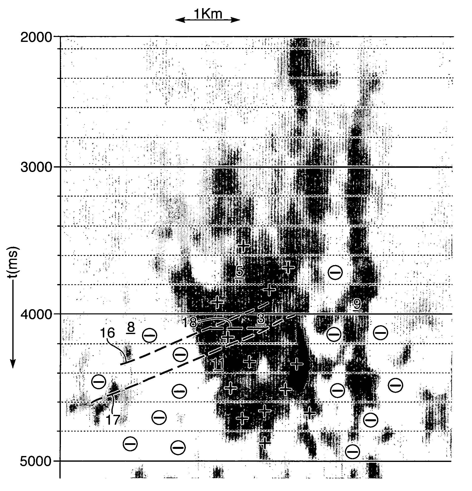
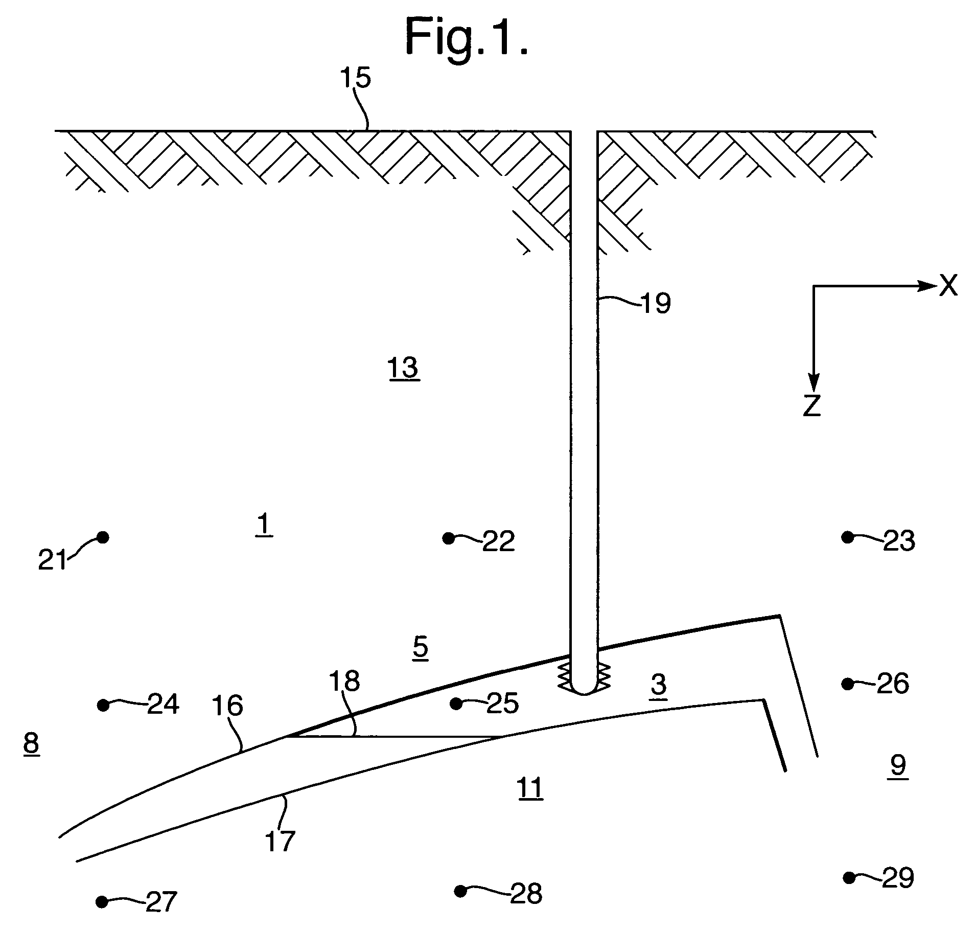
[0024]The present invention is based on the insight gained by applicant that changes in the reservoir pressure give rise to changes in stress in formation regions adjacent to the reservoir region. Since the change in stress in general causes a change in seismic velocity, the change in stress is observable in seismic parameters, such as in the two-way travel time, outside the reservoir region.

[0025]For example, it was realized that depletion in the reservoir region could result in so-called stress arching. Stress arching occurs when a reservoir region is locally compacting, e.g. due to lowering of pore pressure, and when the overburden as a result transfers part of its weight to non compacting or less compacting formation regions laterally surrounding the compacting reservoir region, which results in an arch-like curved distribution of stress.

[0026]One element of the present invention is the recognition that stress distribution changes extend, and are observable in seismic parameters...


PUM


Abstract

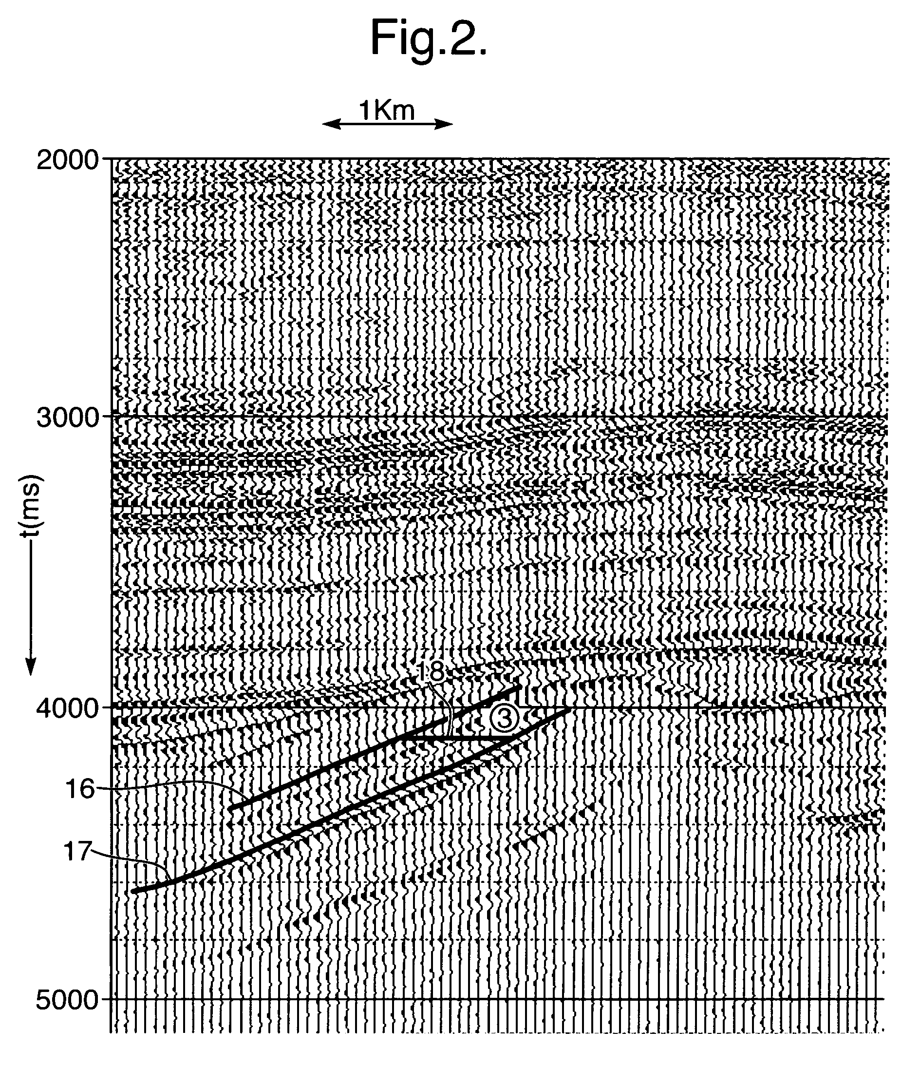
A method of investigating a reservoir region in a subsurface formation by a time-lapse seismic survey. The subsurface formation comprises a further formation region adjacent to the reservoir region. Data are obtained from a time-lapse seismic survey and includes seismic data of the subsurface formation at a first point in time and a later point in time. The seismic data is processed to obtain a seismic representation of change in a predetermined seismic parameter in the further formation region, whereby the seismic parameter is dependent on stress. The seismic representation of change in the seismic parameter in the further formation region is interpreted for an indication of changes of stress distribution in the further formation region, and a property of the reservoir region is derived using the indication of change of stress distribution in the further formation region.

Description

CLAIM TO PRIORITY[0001]This application claims priority based on U.S. Provisional Patent Application No. 60 / 513,955, filed Oct. 24, 2003.FIELD OF THE INVENTION[0002]The present invention relates to a method of investigating a reservoir region in a subsurface formation using a time-lapse seismic survey.BACKGROUND OF THE INVENTION[0003]Time-lapse seismic surveying is increasingly used for studying of earth formations. It is applied for monitoring of hydrocarbon bearing underground reservoirs, in particular to follow the effects resulting from producing reservoir fluids (e.g. oil, gas, water) through a well to surface.[0004]In time-lapse seismic surveying, seismic data are acquired at least two points in time. Time is therefore an additional parameter with regard to conventional seismic surveying. This allows studying the changes in seismic properties of the subsurface as a function of time due to, for example, spatial and temporal variation in fluid saturation, pressure and temperatur...

Claims


Application Information

Patent Timeline
Patent Type & Authority Patents(United States)
IPC IPC(8): G01V1/28G01V1/30G01V1/00
CPCG01V1/30G01V1/32G01V2210/63G01V2210/612
Inventor VAN DEN BEUKEL, ANNEMIEKE CATELIJNEHATCHELL, PAUL JAMESKENTER, CORNELIS JANMARON, KAREL PETERMOLENAAR, MENNO MATHIEUSTAMMEIJER, JOHANNES GIJSBERTUS FRANCISCUS
Owner SHELL USA INC
Learn More