
Control method for switching power supply circuit

a power supply circuit and control method technology, applied in the direction of electric variable regulation, process and machine control, instruments, etc., can solve the problems of low output voltage and transformer excitation noise, and achieve the effect of reducing transformer excitation noise, preventing overcurrent from flowing, and simplifying the control circui

Active Publication Date: 2007-07-10
FUJI ELECTRIC CO LTD
View PDF14 Cites 2 Cited by
  • Summary
  • Abstract
  • Description
  • Claims
  • Application Information

AI Technical Summary

Benefits of technology

The invention provides a switching power supply circuit that reduces transformer excitation noise and prevents overcurrent flow in the switching device. It achieves this by setting two settings values for the exciting current of the transformer: one for the changeover from the switching delay to the switching period and another for the changeover from the switching period to the switching delay. By changing these settings values gradually, the transformer excitation noise is prevented from changing rapidly and the output voltage is prevented from lowering even when the load becomes heavier than it is assumed in the state of light load. Additionally, a capacitor is used to compare the voltage across it with the feedback signal and a comparator is used to make the voltage across the capacitor slowly follow the feedback signal, which further reduces the transformer excitation noise caused by the intermittent switching. Overall, the invention provides a circuit that reduces noise and simplifies the control circuit.

Problems solved by technology

However, the exciting current that flows through the transformer changes greatly at the changeover between the switching period and the switching delay, for which the switching is stopped, causing transformer excitation noise.
However, when the load becomes heavier than assumed, the energies fed to the secondary side of the transformer are insufficient, causing a low output voltage.

Method used


Image

  • Control method for switching power supply circuit
  • Control method for switching power supply circuit
  • Control method for switching power supply circuit

Examples


first embodiment

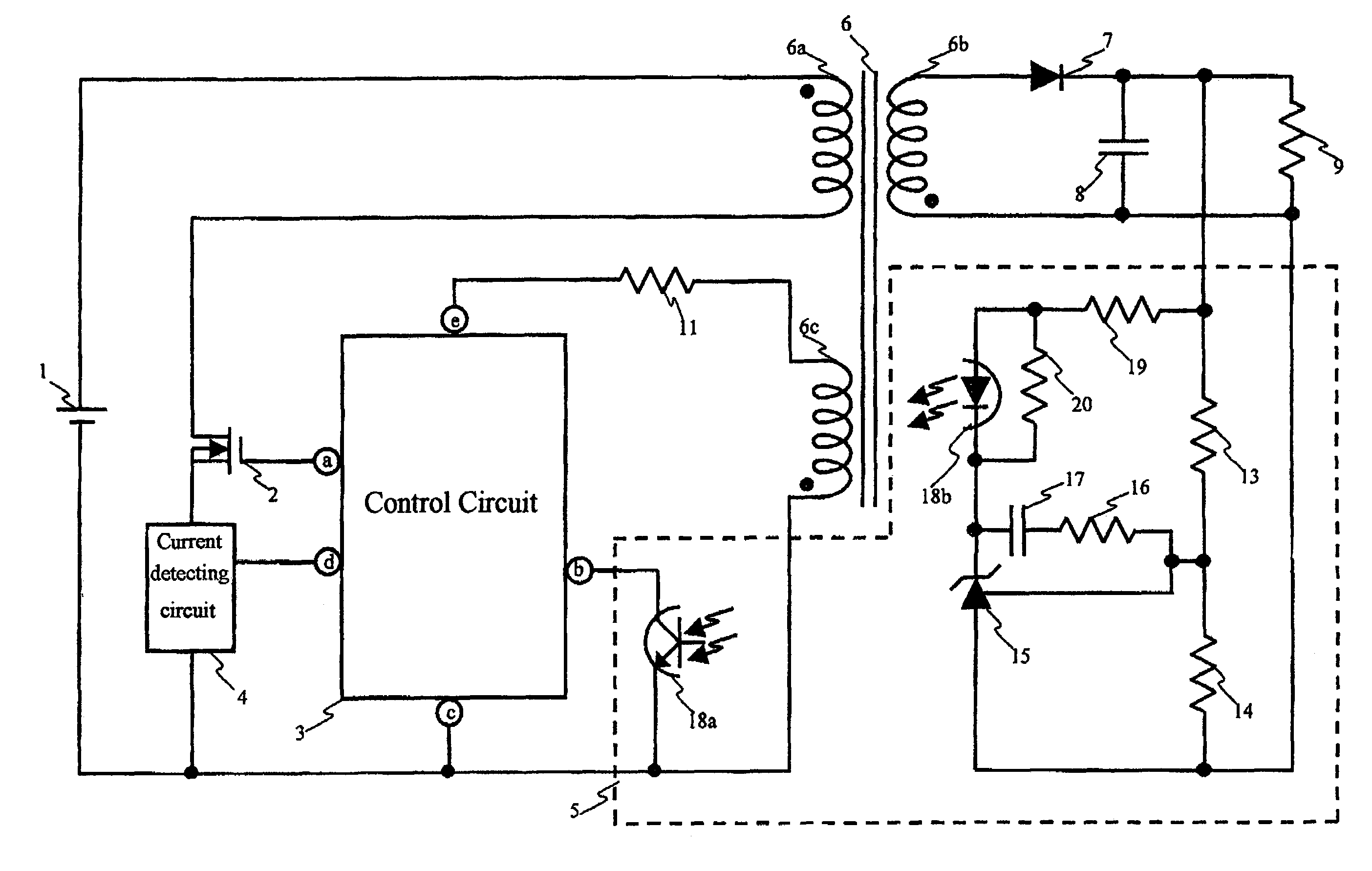
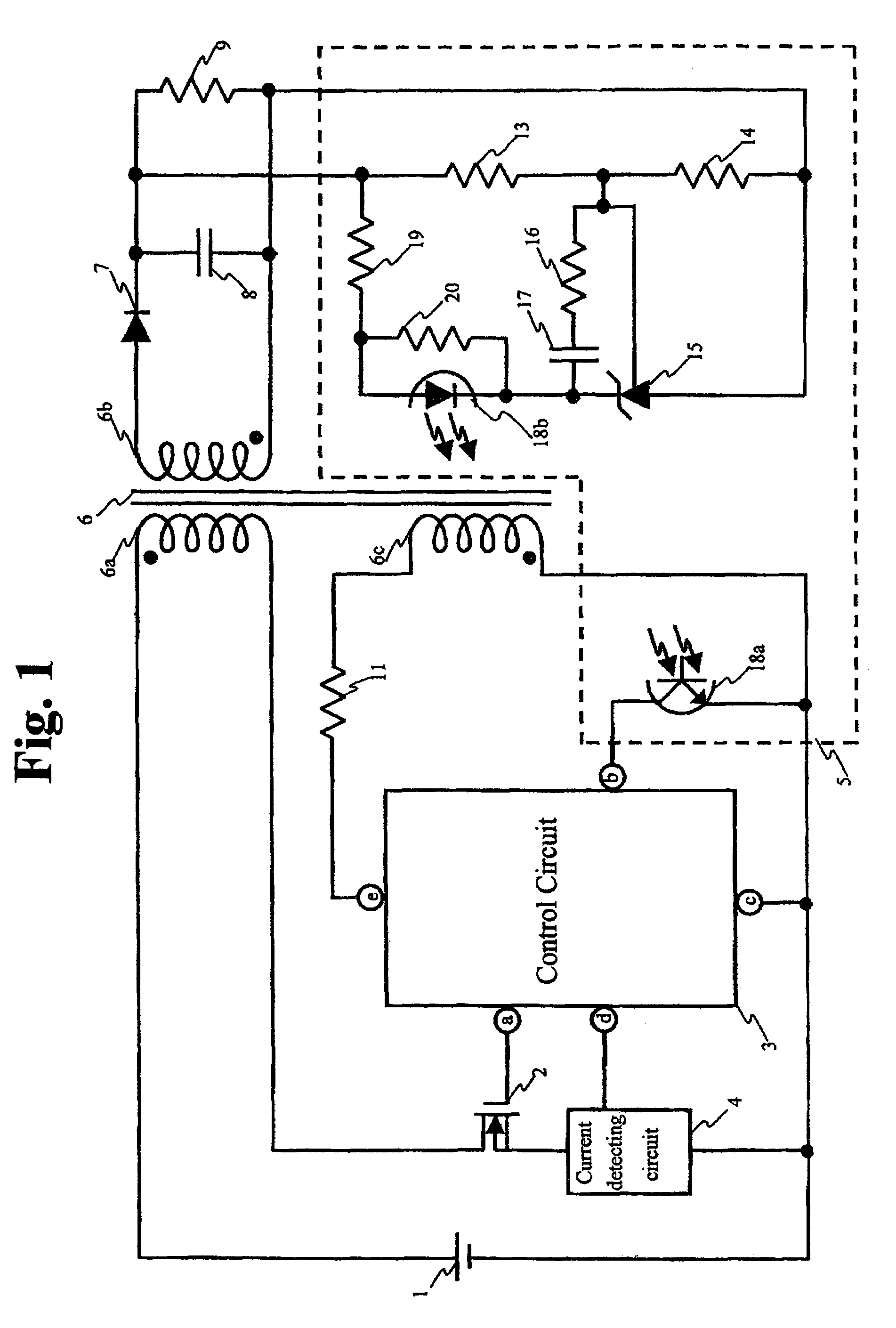
[0044]FIG. 1 is a block circuit diagram of a switching power supply circuit according to the invention.

[0045]Referring now to FIG. 1, the switching power supply circuit according to the first embodiment is different from the conventional switching power supply circuit shown in FIG. 10, in that current detecting resistor 10 in the conventional switching power supply circuit is replaced by a current detecting circuit 4 in the switching power supply circuit. Since the operations of the switching power supply circuit according to the first embodiment are the same with those of the conventional switching power supply circuit shown in FIG. 10, redundant descriptions are omitted.

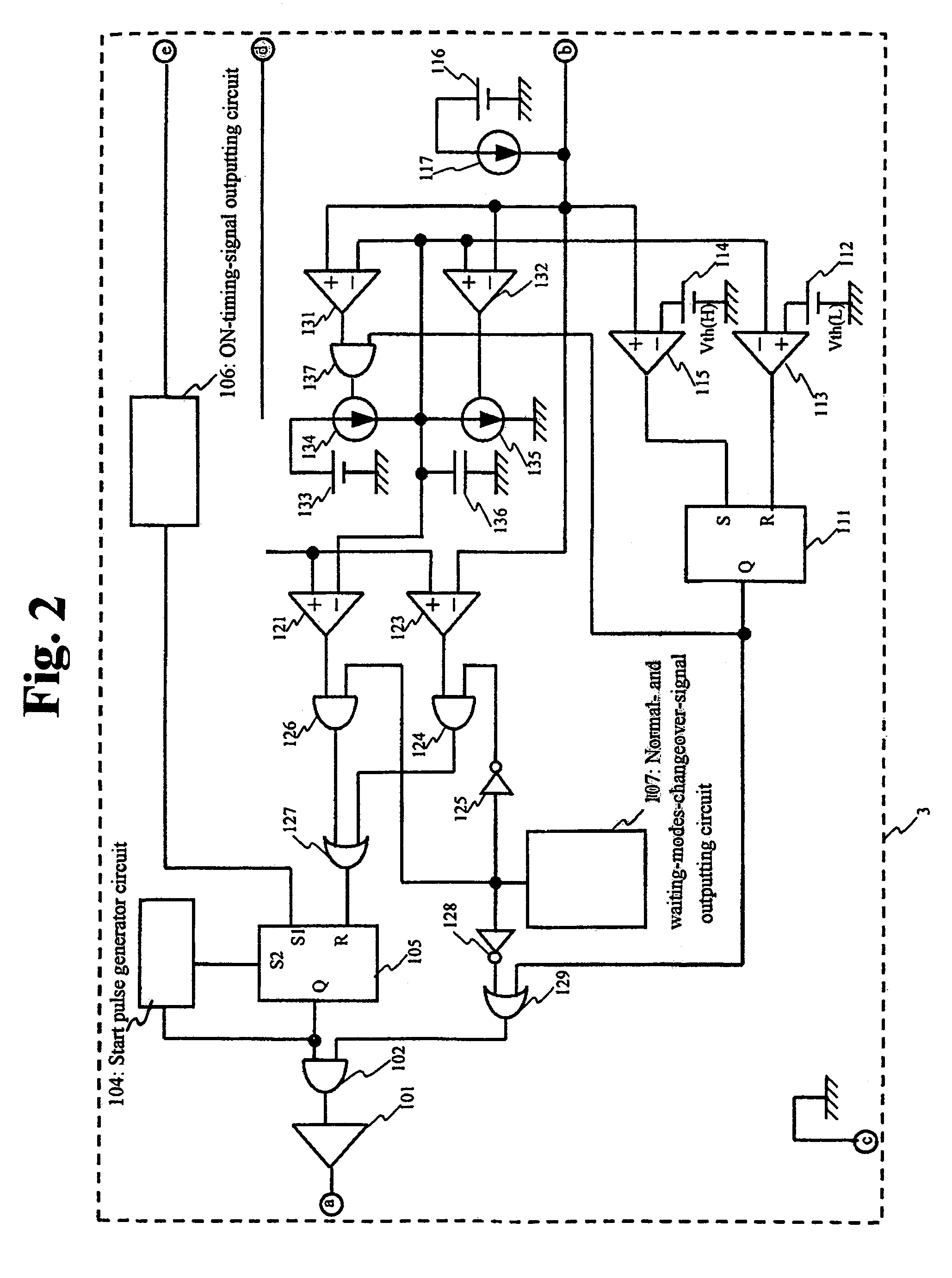
[0046]FIG. 2 is a block circuit diagram of the control circuit shown in FIG. 1. The control circuit shown in FIG. 2 is an improvement of the control circuit shown in FIG. 11. In detail, a NOT gate 128, an OR gate 129, a charging comparator 131 for judging the charging conditions, a discharging comparator 132 for ju...

second embodiment

[0063]FIG. 4 is a block circuit diagram of a control circuit according to the invention.

[0064]The control circuit according to the second embodiment is different from the control circuit according to the first embodiment shown in FIG. 2, in that the output of discharging comparator 132 is connected to changeover-signal outputting circuit 107 in the control circuit shown in FIG. 4. Since the other circuit configurations are the same with those shown in FIG. 2, their duplicated descriptions are omitted.

[0065]At the start of the switching power supply circuit, changeover-signal outputting circuit 107 outputs the waiting mode signal (H-level). Switching start comparator 115 compares the feedback signal with the setting value of constant voltage supply 114. As feedback signal exceeds the switching start voltage Vth (H) set by constant voltage supply 114 to the higher side, switching start comparator 115 sets waiting mode RS flip-flop 111. As waiting mode RS flip-flop 111 is set, OR gate ...

third embodiment

[0072]FIG. 6 is a block circuit diagram of a control circuit according to the invention.

[0073]The control circuit shown in FIG. 6 is different from the control circuit shown in FIG. 2 in that the output of waiting mode RS flip-flop 111 and the output of discharging comparator 132 are connected to changeover-signal outputting circuit 107, and a start signal C(start) and an end signal C(end) are outputted from changeover-signal outputting circuit 107. The control circuit shown in FIG. 6 is different from the control circuit shown in FIG. 2 also in that AND gates 143 and 146; OR gates 142 and 145; NOT gates 144 and 147; and such constituent elements are added.

[0074]Now the operations of the control circuit shown in FIG. 6 will be described below.

[0075]In the waiting mode, changeover-signal outputting circuit 107 keeps the output of the start signal C(start) and the output of the end signal C(end) at the L-level. Since the operations in this case are the same with the waiting mode of op...


PUM


Abstract

A control method for controlling a switching power supply circuit has a control circuit including a setting device that limits the exciting current of a transformer at the time of changeover from a switching delay to a switching period. The setting value set by the setting device is changed slowly to prevent the exciting current of transformer from changing rapidly and to reduce the excitation noise of transformer, and the setting value is changed gradually to prevent the output voltage from lowering even when the load becomes heavier than a certain value during the light load operation. The control method facilitates reducing the electric power consumption of the switching power supply circuit under a light load, reducing the transformer excitation noise and preventing the output voltage from lowering when the load is light.

Description

BACKGROUND OF THE INVENTION AND RELATED ART STATEMENT[0001]The present invention relates to a control method for controlling a switching power supply circuit that has a delay, for which switching is not conducted, to reduce the power consumption thereof when the load is light. Specifically, the present invention relates to a control method that facilitates reducing the transformer excitation noise and stabilizing the switching operations thereof.[0002]Some conventional switching power supply circuits set a switching delay or pause, to stop the switching operations of the switching devices thereof for reducing the power consumption thereof when the load is light. However, the exciting current that flows through the transformer changes greatly at the changeover between the switching period and the switching delay, for which the switching is stopped, causing transformer excitation noise.[0003]Japanese Patent document JP P 2002-136125 A discloses a switching power supply circuit that is...

Claims


Application Information

Patent Timeline
Patent Type & Authority Patents(United States)
IPC IPC(8): H02M3/335
CPCH02M3/33523H02M2001/0032Y02B70/16H02M1/0032Y02B70/10H02M3/28
Inventor FUJITA, KENJINISHIKAWA, YUKIHIRO
Owner FUJI ELECTRIC CO LTD
Learn More