
Pointing device and scanner, robot, mobile communication device and electronic dictionary using the same

a pointing device and scanner technology, applied in the field of pen-type mouse devices, can solve the problems of reducing the sensitivity and precision of the pointing mouse, inconvenient movement of the pen-type mouse, and difficulty in maintaining the sensitivity of the conventional mouse from a mechanical perspective, so as to improve the efficiency of light irradiation and minimize power consumption. , the effect of low power

Active Publication Date: 2007-07-03
KIM IN GWANG
View PDF9 Cites 23 Cited by
  • Summary
  • Abstract
  • Description
  • Claims
  • Application Information

AI Technical Summary

Benefits of technology

[0012]Another object of the present invention is to provide a mouse, which is mechanically simplified.
[0023]Still another object of the present invention is provide a pointing device, which provides a page up / down scroll function using a simple scroll button even in various types of pen-type pointing devices, specifically, provides a scroll function by moving the pen-type pointing device upward and downward, while the scroll button is pressed, to perform a pointing operation.

Problems solved by technology

Therefore, it is inconvenient to move the pen-type mouse, that is, move the pen-type mouse while spacing apart from the tablet by a certain distance.
Such an inconvenience becomes a weak point in a recent trend toward the rapid increase of the utilization of a computer and a mouse.
Therefore, it is difficult to maintain the sensitivity of the conventional mouse from a mechanical perspective.
Therefore, since the pointing sensitivity and precision of the mouse is decreased, such a ball mouse is not suitable for the pen-type mouse.
Further, a pen-type mouse produced in a conventional optical image manner is problematic in that, as the slope of the mouse varies, a distance between an image sensor and a plane varies to deviate a focus, thereby preventing the operation of the mouse from being recognized.

Method used


Image

  • Pointing device and scanner, robot, mobile communication device and electronic dictionary using the same
  • Pointing device and scanner, robot, mobile communication device and electronic dictionary using the same
  • Pointing device and scanner, robot, mobile communication device and electronic dictionary using the same

Examples


Embodiment Construction

[0057]Reference now should be made to the drawings, in which the same reference numerals are used throughout the different drawings to designate the same or similar components.

[0058]An optical image sensor is generally used in optical mice. Currently, in most optical mice, an optical image sensor is used in combination with a lens capable of having a resolution of 400 dpi (dot / inch), and uses 16×16 pixel data per frame as an image required for calculation in an optical part to detect the movement of a ball.

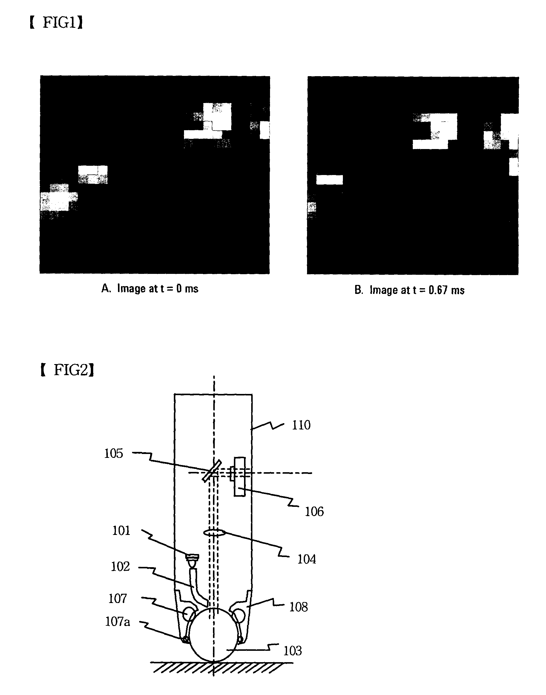
[0059]FIG. 1 illustrates an example of 64 level-gray images as image data input to an optical image sensor (refer to data sheets of Agilent optical mouse Sensors ANDS-2051 and HDNS-2000). The optical image sensor is comprised of an Image Acquisition System (IAS) for acquiring images, a Digital Signal Processor (DSP) for executing signal processing of the acquired images in a digital manner, a function of selecting a PS / 2 mode of the mouse, and an output converter for converting th...


PUM


Abstract

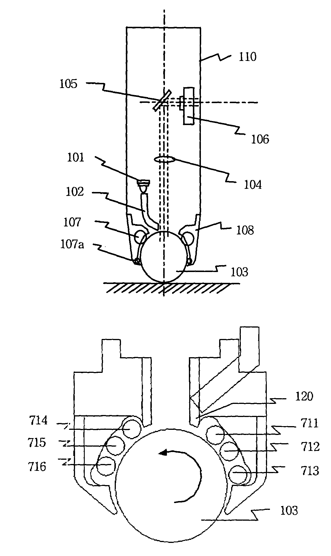
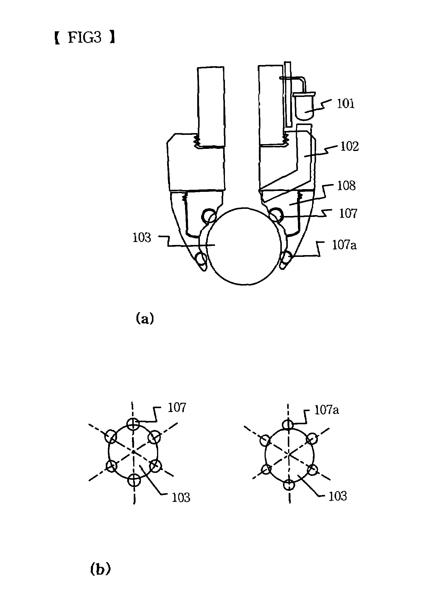
A pointing device is disclosed which does not require a tablet, such as a digitizer, and is mechanically simplified, and a scanner, a robot, a mobile communication device and an electronic dictionary using the pointing device. The pointing device includes a light source, a ball and an optical image sensor. The light source irradiates light. The ball rotates by the movement of the entire pointing device. The optical image sensor detects the movement of the pointing device using an image. The pointing device irradiate light onto the ball through the light source, acquires an image on a surface of the ball through the optical image sensor, and outputs data on movement direction and distance by comparing and analyzing previous and current images.

Description

BACKGROUND OF THE INVENTION[0001]1. Field of the Invention[0002]The present invention relates generally to pointing devices, and more particularly to a pen-type mouse device.[0003]2. Description of the Related Art[0004]A conventional mouse is operated in such a way that a cursor is moved or a click operation is performed by a user moving a mouse on a plane, such as a mouse pad, to rotate a ball of the mouse.[0005]Further, an operation can be carried out using a pen-type mouse instead of a conventional mouse. A pen-type mouse is formed in a pen shape to allow the operation of the mouse to be similar to a handwriting operation of a human being, thus further facilitating the operation of the mouse.[0006]Generally, a pen-type mouse is operated in such a way that a tablet, such as a digitizer, recognizes that the pen-type mouse approaches or comes into contact with the tablet.[0007]Further, the movement of a cursor is not performed by moving the pen-type mouse while bringing the pen-type...

Claims


Application Information

Patent Timeline
Patent Type & Authority Patents(United States)
IPC IPC(8): G09G5/08G06K9/62G06F1/16G06F3/033G06F3/038G06F3/041H04M1/02
CPCG06F1/1626G06F3/03546G06F3/0312G06F1/169
Inventor KIM, IN-GWANG
Owner KIM IN GWANG
Learn More