
High frequency amplifier circuit and mobile communication terminal using the same

a high frequency amplifier and mobile communication technology, applied in the field of high frequency amplifier circuits, can solve the problems of increasing the circuit size of the high frequency circuit block, the relation between the gain control voltage and the amount of attenuation in the gain control circuit, and the complexity of the control circuit, so as to achieve the effect of improving the distortion characteristics

Inactive Publication Date: 2007-07-03
PANASONIC CORP
View PDF16 Cites 3 Cited by
  • Summary
  • Abstract
  • Description
  • Claims
  • Application Information

AI Technical Summary

Benefits of technology

The design simplifies the control circuit, expands the range of gain control settings, and reduces frequency-dependent variations, enabling efficient operation across multiple communication schemes without the need for high-resolution D / A converters.

Problems solved by technology

A first problem is that in the gain control circuit according to the prior art, two kinds of control signals are necessary for controlling the gain control circuit, and hence causes complexity in the control circuit.
This increases the circuit size of the high frequency circuit block.
A second problem is that in the gain control circuit according to the prior art, the gain control circuit can merely take two states having a low impedance and a high impedance.
A third problem is that when a high frequency amplifier circuit supporting a plurality of communication schemes is constructed, the relation between the gain control voltage and the amount of attenuation in the gain control circuit varies depending on the communication scheme because of the frequency characteristics of the gain control circuit.
A fourth problem is that when a gain control circuit used in a high frequency amplifier circuit supporting a plurality of communication schemes and having different frequencies depending on the communication schemes is constructed, a D / A converter connected to a control terminal needs a higher resolution in the output voltage in case that the control voltage and the gain control characteristics vary depending on the frequency.
This causes an increase in the circuit size of the D / A converter in the control circuit and in the number of the control parameters for the gain control voltage and the amount of attenuation used for controlling the gain control circuit.
This causes complexity in the control circuit.

Method used


Image

  • High frequency amplifier circuit and mobile communication terminal using the same
  • High frequency amplifier circuit and mobile communication terminal using the same
  • High frequency amplifier circuit and mobile communication terminal using the same

Examples


embodiment 1

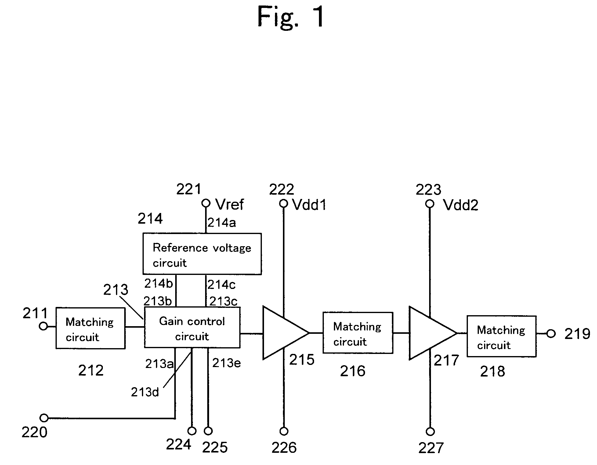
[0162]FIG. 1 is a block diagram showing the configuration of a high frequency amplifier circuit according to Embodiment 1 of the invention. The high frequency amplifier circuit of FIG. 1 corresponds to the high frequency amplifier circuit 202 shown in the block diagram of FIG. 8 illustrating a transmitting section of a prior art portable telephone terminal. That is, in the portable telephone terminal according to the embodiment of the invention, the high frequency amplifier circuit of FIG. 1 is used in place of the high frequency amplifier circuit 202 in the transmitting section of the prior art portable telephone terminal of FIG. 8.

[0163]The high frequency amplifier circuit of FIG. 1 is described below in detail.

[0164]In FIG. 1, a high frequency signal inputted through a signal input terminal 211 is provided through a matching circuit 212 for impedance transformation to a gain control circuit 213. The output signal of the gain control circuit 213 is inputted to an amplifier 215, an...

embodiment 2

[0211]FIG. 5 is a block diagram showing the configuration of a high frequency amplifier circuit according to Embodiment 2 of the invention. The high frequency amplifier circuit of FIG. 5 corresponds to the high frequency amplifier circuit 202 shown in the block diagram of FIG. 8 illustrating a transmitting section of a prior art portable telephone terminal. That is, in the portable telephone terminal according to the embodiment of the invention, the high frequency amplifier circuit of FIG. 5 is used in place of the high frequency amplifier circuit 202 in the transmitting section of the prior art portable telephone terminal of FIG. 8.

[0212]The high frequency amplifier circuit of FIG. 5 is described below in detail.

[0213]In FIG. 5, a high frequency signal inputted through a signal input terminal 271 is provided through a matching circuit 272 for impedance transformation to a gain control circuit 273 having a voltage divider circuit. The output signal of the gain control circuit 273 is...


PUM


Abstract

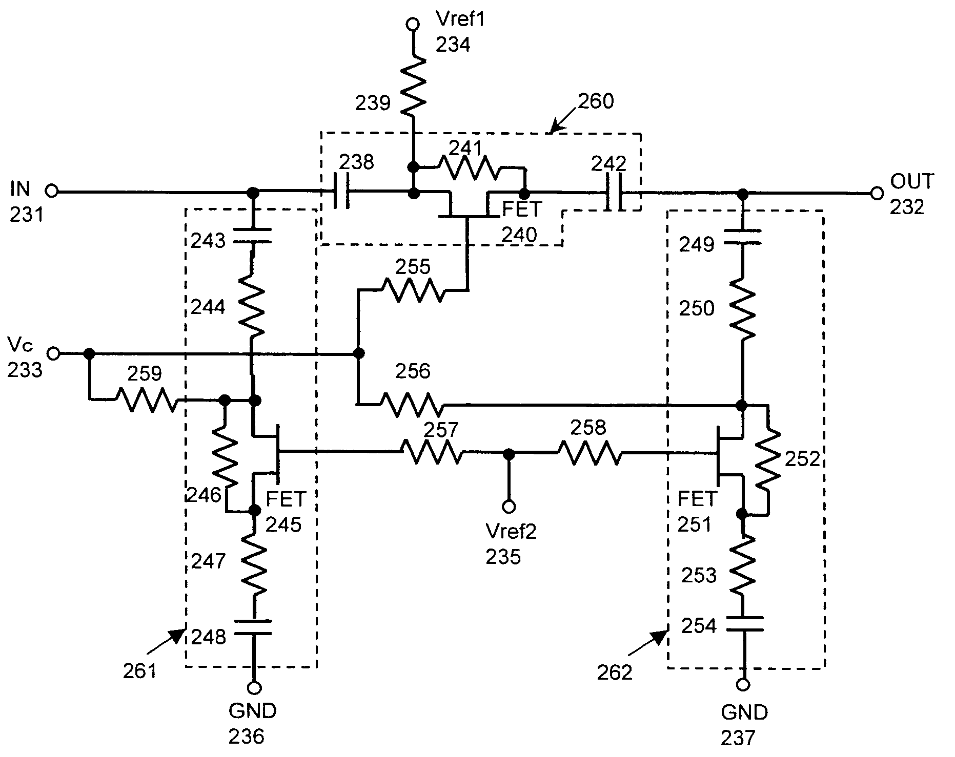
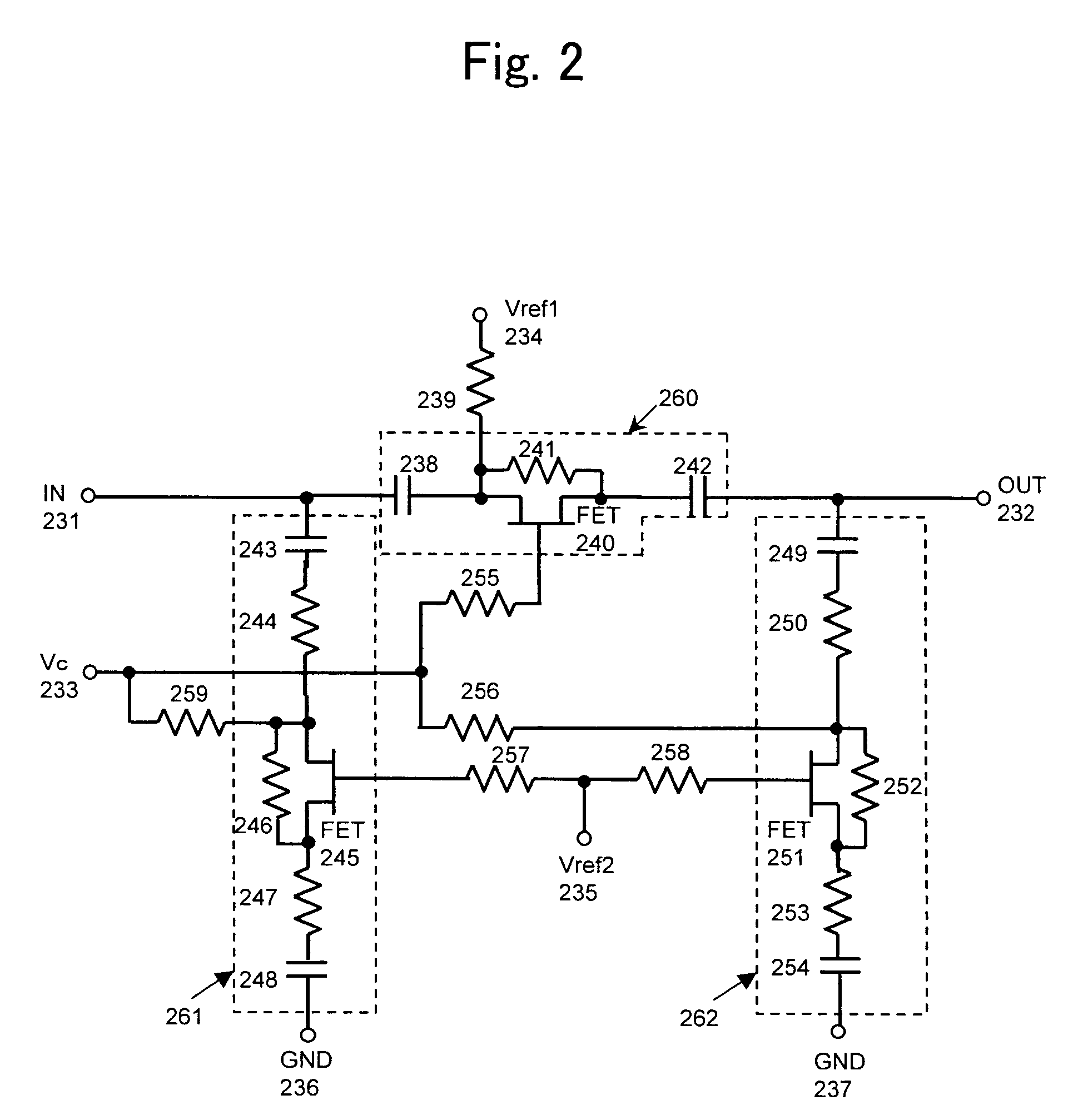
A first FET is inserted in a series position between a signal input terminal and a signal output terminal, while second and third FETs are inserted in a shunt position respectively between the signal input terminal and a ground terminal and between the signal output terminal and a ground terminal. First and second reference voltage terminals and a control terminal are provided. A first reference voltage and a control voltage are applied to the first FET, while a second reference voltage and a control voltage are applied respectively to the second and third FETs, so that the first, second, and third FETs serve as variable resistors. As such, a gain control circuit is constructed. Further, a first resistor is provided in parallel to the first FET, while second and third resistors are provided respectively in series to the second and third FETs.

Description

BACKGROUND OF THE INVENTION[0001]1. Field of the Invention[0002]The present invention relates to a high frequency amplifier circuit which is provided in a high frequency circuit section of a transmitting section of a mobile communication terminal so as to amplify a high frequency signal. The invention further relates to a mobile communication terminal using the high frequency amplifier circuit. The circuit addressed in the invention is such a high frequency amplifier circuit that the output power thereof is controlled by a control voltage.[0003]2. Related Art of the Invention[0004]Recently, in the field of mobile communication, combined portable telephone terminals where a plurality of communication schemes are integrated are entering into the mainstream of mobile communication terminals. An example of this is a mobile communication terminal that supports both PDC (Personal Digital Cellular) and W-CDMA (Wide band Code Division Multiple Access) schemes. Such a combined mobile communi...

Claims


Application Information

Patent Timeline
Patent Type & Authority Patents(United States)
IPC IPC(8): H03K3/04H03H7/25H03F3/195H03G1/00H03G3/10H03G3/20H03G3/30H03H11/24H04B1/04H04B1/3822H04B1/40
CPCH03G1/007H03G3/3042H03F2200/72H04B2001/0416
Inventor NAKAYAMA, MASAOTAKAGI, TSUNEHIROINAMORI, MASAHIKOMOTOYOSHI, KANAME
Owner PANASONIC CORP
Learn More