
Fine resolution pulse width modulation pulse generator for use in a multiphase pulse width modulated voltage regulator

a voltage regulator and multi-phase technology, applied in pulse technique, dc-dc conversion, power conversion systems, etc., can solve the problems of increasing the demands on the power regulation system, the power requirements of emerging leading edge technology microprocessors are difficult to meet, and the operating voltage decreases, so as to improve the performance of digital multi-phase voltage regulators and high precision pulse width control. , the effect of high resolution

Active Publication Date: 2007-07-03
INFINEON TECH AUSTRIA AG
View PDF4 Cites 35 Cited by
  • Summary
  • Abstract
  • Description
  • Claims
  • Application Information

AI Technical Summary

Benefits of technology

This approach enables high-resolution and high-precision pulse width control, reducing quantization errors and enhancing the performance of digital multiphase voltage regulators, effectively addressing the challenges of regulating microelectronic devices with complex power requirements.

Problems solved by technology

Power requirements for emerging leading edge technology microprocessors have become very difficult to satisfy.
As the speed and integration of microprocessors increases, the demands on the power regulation system increase.
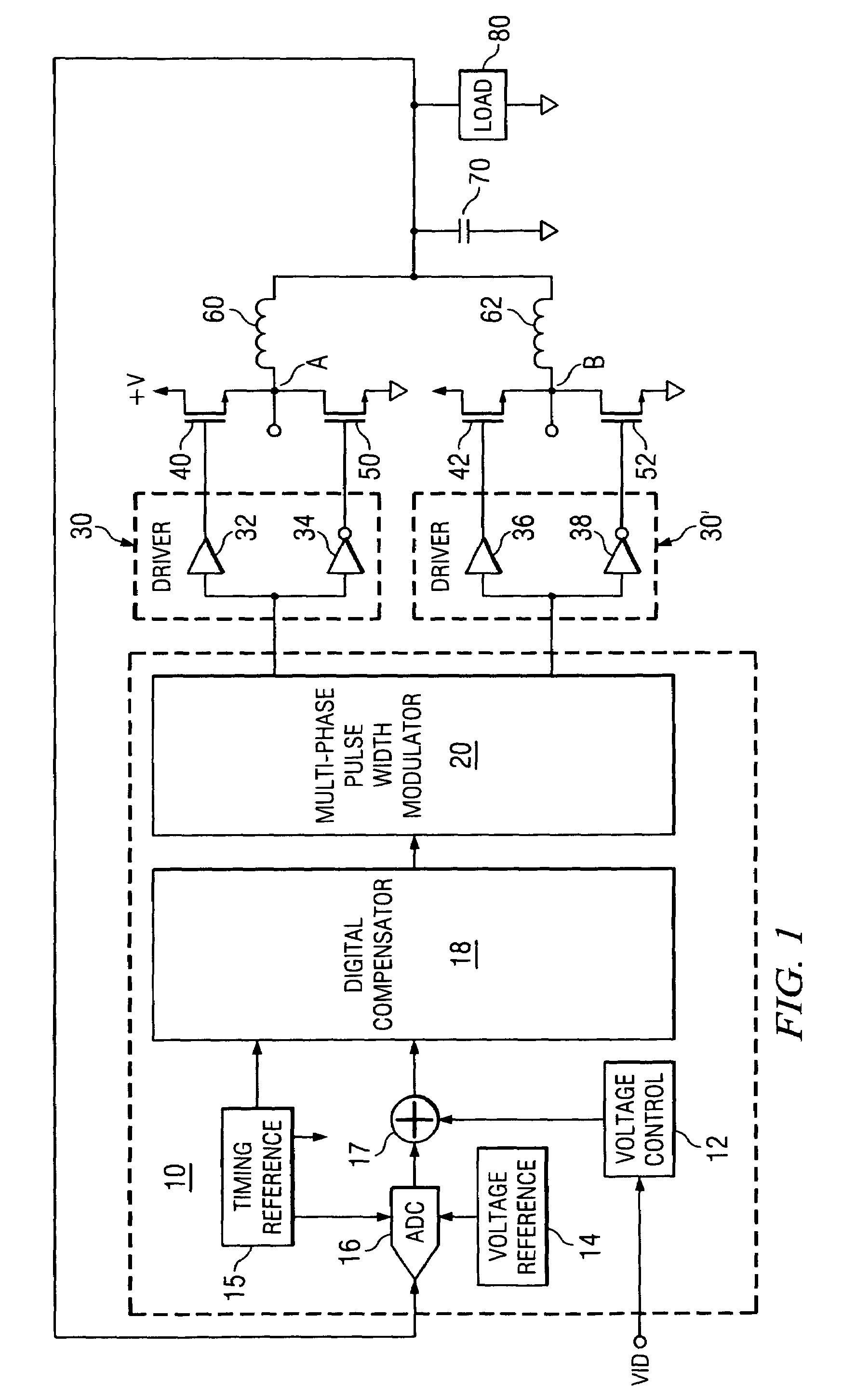
In particular, as gate counts increase, the power regulation current demand increases, the operating voltage decreases and transient events (e.g. relatively large voltage spikes or droops at the load) typically increase in both magnitude and frequency.
However, one of the difficulties in implementing digital multiphase buck converters is in the generation of precise width pulses to control the power switch.
Since the width of the pulse has a direct impact on the voltage at the load, it is a key performance limiter if the system is unable to generate a pulse width with the desired precision.
Since the width of the pulse generated in this manner is discrete, there is a quantization error associated with each pulse width.
This technique however is limited when the technology will not support a higher clock frequency.
This technique is primarily limited by the inability to control the delay in this fine resolution delay generator, so that the controller is not able to generate the desired pulse width with high precision.

Method used


Image

  • Fine resolution pulse width modulation pulse generator for use in a multiphase pulse width modulated voltage regulator
  • Fine resolution pulse width modulation pulse generator for use in a multiphase pulse width modulated voltage regulator
  • Fine resolution pulse width modulation pulse generator for use in a multiphase pulse width modulated voltage regulator

Examples


Embodiment Construction

[0058]The present invention may be described herein in terms of various functional components and various processing steps. It should be appreciated that such functional components may be realized by any number of hardware or structural components configured to perform the specified functions. For example, the present invention may employ various integrated components comprised of various electrical devices, e.g. resistors, transistors, capacitors, inductors and the like, whose values may be suitably configured for various intended purposes. Any actual values provided for such components as well as applied voltage levels and currents are intended by way of example and not limitation.

[0059]In addition, the present invention may be practiced in any integrated circuit application. Such general applications and other details that will be apparent to those skilled in the art in light of the present disclosure are not described in detail herein. Further, it should be noted that while vari...


PUM


Abstract

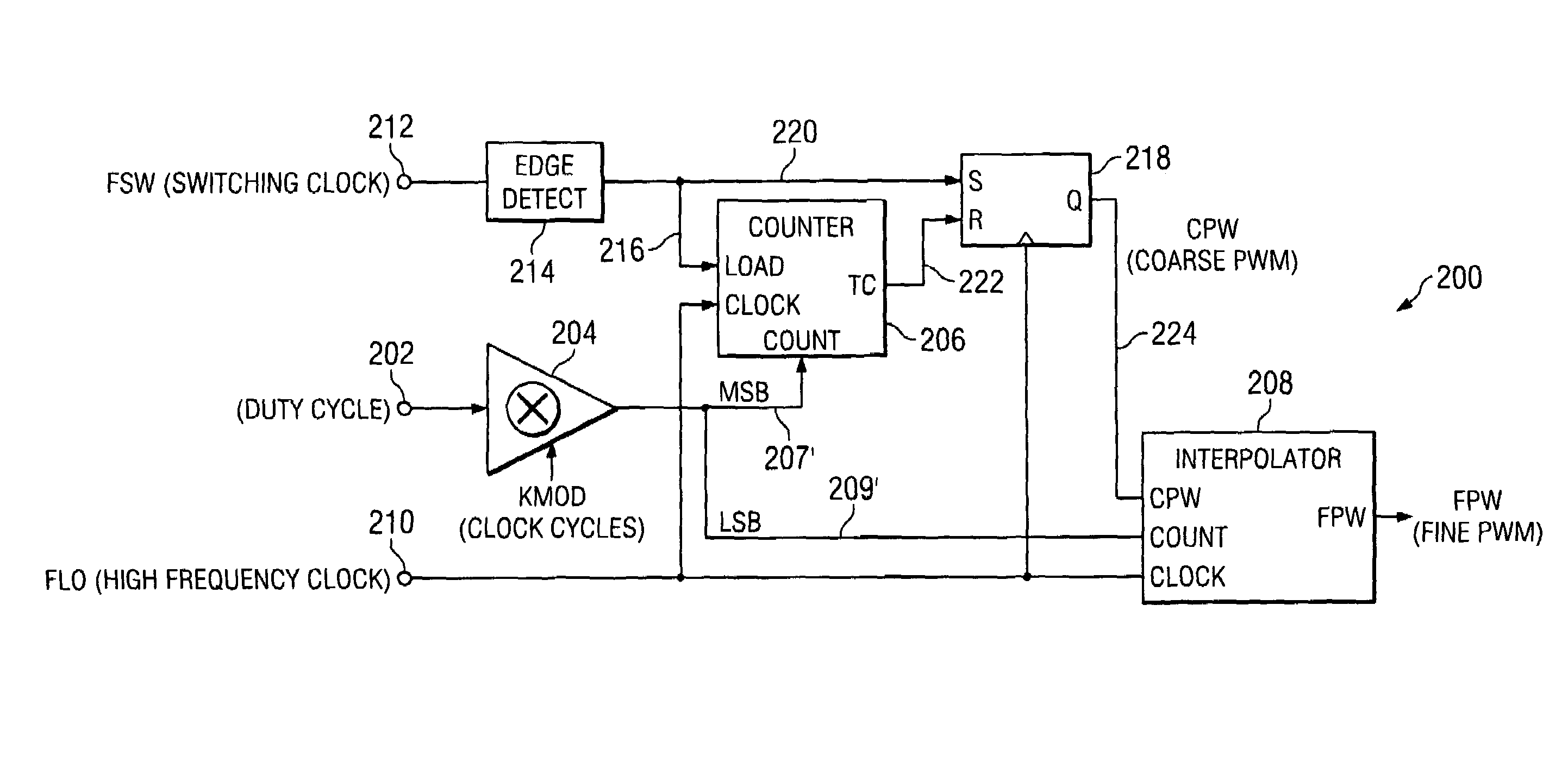
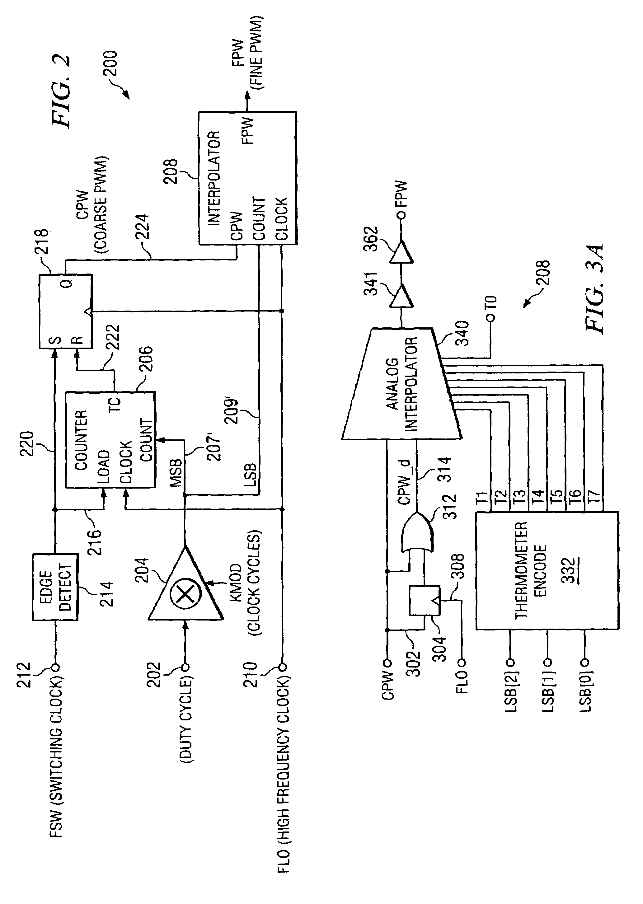
Disclosed is a fine resolution pulse width generator for use in a multiphase pulse width modulated voltage regulator. The fine pulse width is generated by first generating a pulse with a coarse pulse width and one or more delayed replicas thereof. Then, digitally controlled analog interpolators are used to generate the fine resolution pulse width pulse by interpolating among the coarse pulse width pulses. Both single edge and double edge modulation embodiments are disclosed providing interpolation of just the trailing edges of the coarse pulses or both the leading and trailing edges, respectively. The disclosed fine resolution pulse generator uses counters, thermometer encoders and analog interpolators to achieve interpolation accurately by insuring that each interpolation step corresponds to an equal weight. Accuracy of the interpolation is defined by the linearity (i.e. how well the interpolation fits a best fit straight line) and monotonicity (i.e. how each step contributes a positive weight to the total).

Description

CROSS REFERENCES TO RELATED PATENT APPLICATIONS AND PATENTS[0001]This application includes subject matter that is related to and claims priority from the following patent applications, commonly assigned to the assignee of the present application, that are hereby incorporated herein by reference:[0002]1. SYSTEM AND METHOD FOR HIGHLY PHASED POWER REGULATION, Ser. No. 10 / 112,738 filed Apr. 1, 2002, inventors: Duffy, et al, now U.S. Pat. No. 6,563,294.[0003]2. SYSTEM, DEVICE AND METHOD FOR PROVIDING VOLTAGE REGULATION TO A MICROELECTRONIC DEVICE, Ser. No. 10 / 103,980, filed Mar. 22, 2002, inventors: Duffy et al.[0004]3. SYSTEM AND METHOD FOR CURRENT HANDLING IN A DIGITALLY CONTROLLED POWER CONVERTER, Ser. No. 10 / 237,903, filed Sep. 9, 2002, inventors: Duffy et al, now U.S. Pat. No. 6,795,009.[0005]4. SYSTEM AND METHOD FOR HIGHLY PHASED POWER REGULATION USING ADAPTIVE COMPENSATION CONTROL, Ser. No. 10 / 109,801, filed Oct. 15, 2001, inventors: Goodfellow et al.[0006]5. DIGITAL CALIBRATION W...

Claims


Application Information

Patent Timeline
Patent Type & Authority Patents(United States)
IPC IPC(8): G05F1/40
CPCH02M3/157H02M3/1584H03K17/005H03K17/6871
Inventor TANG, BENJAMIN
Owner INFINEON TECH AUSTRIA AG
Learn More