Eureka AIR delivers breakthrough ideas for toughest innovation challenges, trusted by R&D personnel around the world.

Recording device, reproduction device, and recording/reproduction device

a recording device and a technology for reproduction devices, applied in the direction of optical recording/reproducing/erasing methods, optical beam sources, instruments, etc., can solve the problems of deterioration of s/n ratio and low reproduction signal level, and achieve good s/n ratio reproduction, high quality data recording and reproduction, and large amplitude modulation

Inactive Publication Date: 2007-06-26
PIONEER CORP
View PDF6 Cites 14 Cited by
  • Summary
  • Abstract
  • Description
  • Claims
  • Application Information

AI Technical Summary

Benefits of technology

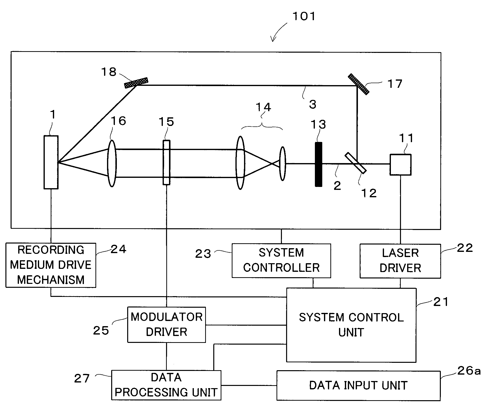
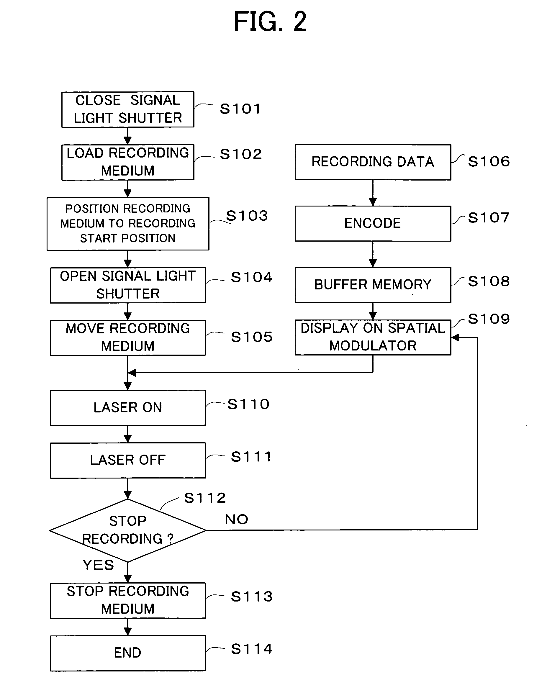
[0010]One of features of the first recording apparatus according to the present invention is that the pulse oscillation laser of high oscillation power is used as a light source, and the pulse oscillation timing of this laser is controlled by the pulse oscillation controlling device, and this control can be also performed under an external device. Thereby, the interference fringes, which form a hologram for example, can be generated with high power for a short time, so that the high quality data recording with the large amplitude modulation can be achieved. Due to this effect, the interference pattern with a large amplitude modulation can be generated, even in the case that the recording medium moves relative to the signal light and the reference light. Therefore, the high quality data recording can be performed on a rotating disk-shaped recording medium for example. This is suitable for recording the continuous information such as music or video.
[0043]One of features of the second recording reproduction apparatus according to the present invention is that the continuous oscillation laser is used as the light source, and the irradiation time and the timing of the signal light and the reference light are controlled by the optical shutter controlling device, and this control can be also performed under an external device. The irradiation time of the light beam having a power sufficient to generate the interference fringes, which form a hologram for example, can be controlled, so that the data recording is achieved with a large amplitude modulation and a good S / N ratio reproduction is achieved. Therefore, the high quality data recording and reproduction can be achieved even in the case that the recording medium moves relative to the signal light or the reference light during recording or reproduction. This is suitable for recording and reproduction the continuous information such as music or video. Furthermore, using the continuous oscillation laser improves handling of the light source. For example, a circuit related to the light source can be simplified.

Problems solved by technology

However, in the case that data is continuously recorded in a situation that a position of the recording medium changes relative to positions of the signal light and the reference light, the interference pattern produced by the two-dimensional image corresponding to the recording data and the reference light is recorded while moving in the recording medium.
Therefore, the reproduction signal level becomes low and the S / N ratio is deteriorated.

Method used


Image

  • Recording device, reproduction device, and recording/reproduction device
  • Recording device, reproduction device, and recording/reproduction device
  • Recording device, reproduction device, and recording/reproduction device

Examples


first embodiment

OF RECORDING REPRODUCTION APPARATUS

[0112]The first embodiment of the recording reproduction apparatus according to the present invention will be discussed, with reference to FIG. 11. In this embodiment, a pulse oscillation laser is used as a light source, and it is possible to generate interference fringes, which form a hologram for example, corresponding to two-dimensional image data of recording data with high amplitude modulation, and to reproduce the data showing good S / N ratio.

[0113]Incidentally, the recording reproduction apparatus of the embodiment discussed below is preferably a hologram recording reproduction apparatus for recording information as interference fringes, i.e. a light interference pattern, into the hologram recording medium, and reproducing the information recorded as the interference fringes, i.e. the light interference pattern.

[0114]As shown in FIG. 11, the recording reproduction apparatus 103 of the embodiment is provided with: an optical system including a...

second embodiment

OF RECORDING REPRODUCTION APPARATUS

[0127]The second embodiment of the recording reproduction apparatus according to the present invention will be discussed, with reference to FIG. 12. In the embodiment, a continuous oscillation laser is used as a light source, and it is possible to generate interference fringes in the recording medium with the high intensity amplitude from a reference light and two-dimensional image data corresponding to recording data and to reproduce the data showing good S / N ratio, even in the case that the recording medium moves relative to the signal light and the reference light.

[0128]Incidentally, the recording reproduction apparatus of the embodiment discussed below is preferably a hologram recording reproduction apparatus for recording information as interference fringes, i.e. a light interference pattern, into a hologram recording medium, and reproducing the information recorded as the interference fringes, i.e. the light interference pattern, from the hol...


PUM

PropertyMeasurementUnit
refractive indexaaaaaaaaaa
pulse widthaaaaaaaaaa

Abstract

An example recording apparatus includes a pulse oscillation laser, a half mirror for splitting the pulse oscillation light of the laser into a signal light and a reference light, an optical shutter disposed in the optical path of the signal light, a beam expander for converting the signal light into a light beam of a predetermined diameter, a spatial modulator for modulating the recording data into two-dimensional image information, a Fourier Transform lens for introducing the signal light modulated by the spatial modulator onto a recording medium, mirrors for introducing the reference light onto the recording medium with a predetermined angle, a system control unit, a laser driver, a system controller, a recording medium drive mechanism, a modulator driver, a data input unit, and a data processing unit.

Description

[0001]This application is the US national phase of international application PCT / JP03 / 09600 filed 29 Jul. 2003 which designated the U.S. and claims benefit of JP 2002-223465, dated 31 Jul. 2002, the entire contents of each of which are hereby incorporated by reference.TECHNICAL FIELD[0002]The present invention relates to a recording apparatus, a reproduction apparatus and a recording reproduction apparatus for recording data in a recording medium and reproducing the data, such as a hologram recording apparatus, a hologram reproduction apparatus and a hologram recording reproduction apparatus for recording data in a hologram recording medium and reproducing the data.BACKGROUND ART[0003]Recently, a recording medium capable of recording a three-dimensional interference pattern as a spatial change of the refractive index in the inside thereof receives attention. For example, a photorefractive crystal receives attention, which is a photosensitive medium such as lithium niobate (NbO3, abb...

Claims


Application Information

Patent Timeline
Patent Type & Authority Patents(United States)
IPC IPC(8): G11B7/00G03H1/16G03H1/26G11B7/0065G11B7/126G11B7/128
CPCG03H1/16G03H1/26G11B7/0065G11B7/126G11B7/128G03H2222/33
Inventor TANAKA, SATORUITOH, YOSHIHISATACHIBANA, AKIHIROKUBOTA, YOSHIHISA
Owner PIONEER CORP
Why Eureka
Eureka Blog
Learn More