Tunable dispersion compensator

a wavelength dispersion and compensator technology, applied in the field of wavelength dispersion compensation, can solve the problems of high dispersion compensation cost, significant degrade reception level, and difficulty in performing dispersion compensation in a reconfigurable wdm network with a dcf whose compensation valu

Inactive Publication Date: 2007-06-12
FUJITSU LTD
View PDF16 Cites 4 Cited by
  • Summary
  • Abstract
  • Description
  • Claims
  • Application Information

AI Technical Summary

Problems solved by technology

This phenomenon is called wavelength dispersion, which significantly degrades the reception level.
Therefore, it would be difficult to perform dispersion compensation in a reconfigurable WDM network with a DCF whose compensation value is fixed.
As shown in the drawing, to achieve dispersion compensation of the plurality of channels by using the tunable dispersion compensators 1400 of the first example of the conventional technology, light has to be dispersed in advance at channel intervals, and also a large number of tunable dispersion compensators 1400 corresponding to the channels have to be connected, thereby requiring high dispersion compensation cost.
Therefore, it is difficult to maintain the shapes of the mirrors 1602a through 1602n for a long time because the material forming the mirrors is fatigued, deteriorated with time, or the like.
Therefore, a special detecting mechanism has to be required, thereby increasing cost.
In this case, the module is disadvantageously large in size.
In the technology of the first example of the conventional technology, however, there is a problem that the amount of wavelength dispersion compensation cannot be set for each channel separately.
Moreover, to make the amount of compensation tunable, the entire free surface mirror 1406 has to be shifted, thereby making it impossible to quickly perform an operation when the amount of compensation is changed.

Method used


Image

  • Tunable dispersion compensator
  • Tunable dispersion compensator
  • Tunable dispersion compensator

Examples


Embodiment Construction

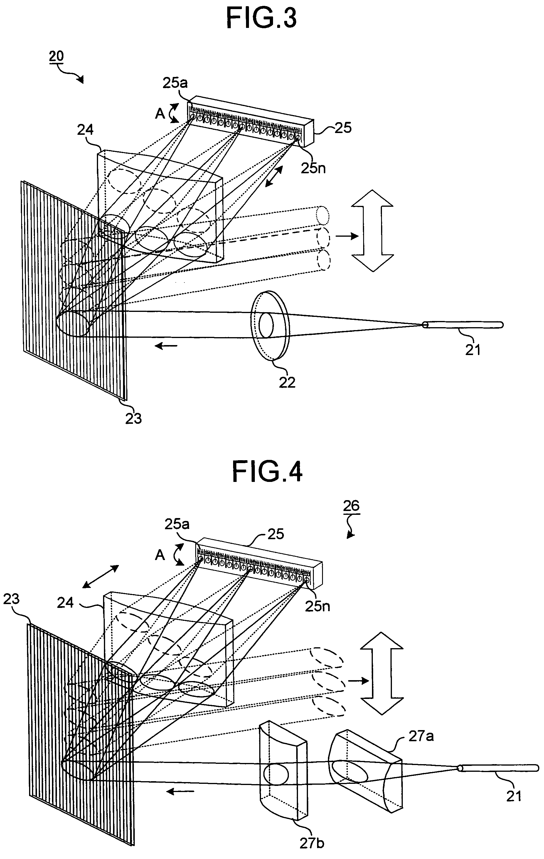
[0042]Exemplary embodiment of a tunable dispersion compensator according to the present invention is described in detail below with reference to the accompanying drawings.

[0043]The present invention relates to a channel-by-channel (Ch-by-Ch) tunable dispersion compensator achieving dispersion compensation of a plurality of channels (Ch) with a single module. To achieve this Ch-by-Ch tunable dispersion compensator, the following three functions have to be satisfied as basic functions.

[0044]A first function is to allow a wavelength-multiplexed signal to be demultiplexed by channel. A second function is to allow the amount of compensation to be set for each channel. For example, the light traveling direction can be changed between a short wavelength side and a long wavelength side. A third function is to allow optical path difference to be continuously given between the short wavelength side and the long wavelength side within a wavelength range included in the channel.

[0045]In the pre...


PUM


Abstract

A tunable dispersion compensator includes a collimating unit that collimates an incident light to output a parallel light, a parallel shifting unit that spatially shifts the parallel light from the collimating unit within a predetermined range, and an optical-path-length providing unit that provides optical path length of light corresponding to a position at which light output from the parallel shifting unit is input.

Description

CROSS-REFERENCE TO RELATED APPLICATIONS[0001]This application is based upon and claims the benefit of priority from the prior Japanese Patent Application No. 2004-102696, filed on Mar. 31, 2004, the entire contents of which are incorporated herein by reference.BACKGROUND OF THE INVENTION[0002]1) Field of the Invention[0003]The present invention relates to a technology for compensating wavelength dispersion in optical fiber transmission.[0004]2) Description of the Related Art[0005]Conventionally, in optical signal pulse transmission using an optical fiber, the transmission speed in the fiber varies according to the wavelength. Therefore, as the transmission distance extends, the signal pulse wave becomes blunt. This phenomenon is called wavelength dispersion, which significantly degrades the reception level. For example, in single mode fiber (SMF), wavelength dispersion of 15–16 ps / nm / km occurs near a wavelength of 1.55 micrometers. One of the ways of compensating such wavelength dis...

Claims


Application Information

Patent Timeline
Patent Type & Authority Patents(United States)
IPC IPC(8): G02B6/26G02B26/06G02B6/34G02B27/00G02B27/10G02B27/42
CPCG02B6/2931G02B6/29311G02B6/29358G02B6/29394G02B6/29395G02B27/0068G02B27/1086G02B27/143G02B27/145G02B27/42G02B27/4277
Inventor SHIBATA, KOHEI
Owner FUJITSU LTD
Why Eureka
Try Eureka