
Method for the production of a bristle structure on a carrier

a manufacturing method and bristle technology, applied in the direction of brushes, domestic objects, moulds, etc., can solve the problems of insufficient fatigue strength of injection molded bristles under reverse bending stresses, limited application, and increased costs

Active Publication Date: 2007-06-05
GEKA
View PDF12 Cites 38 Cited by
  • Summary
  • Abstract
  • Description
  • Claims
  • Application Information

AI Technical Summary

Benefits of technology

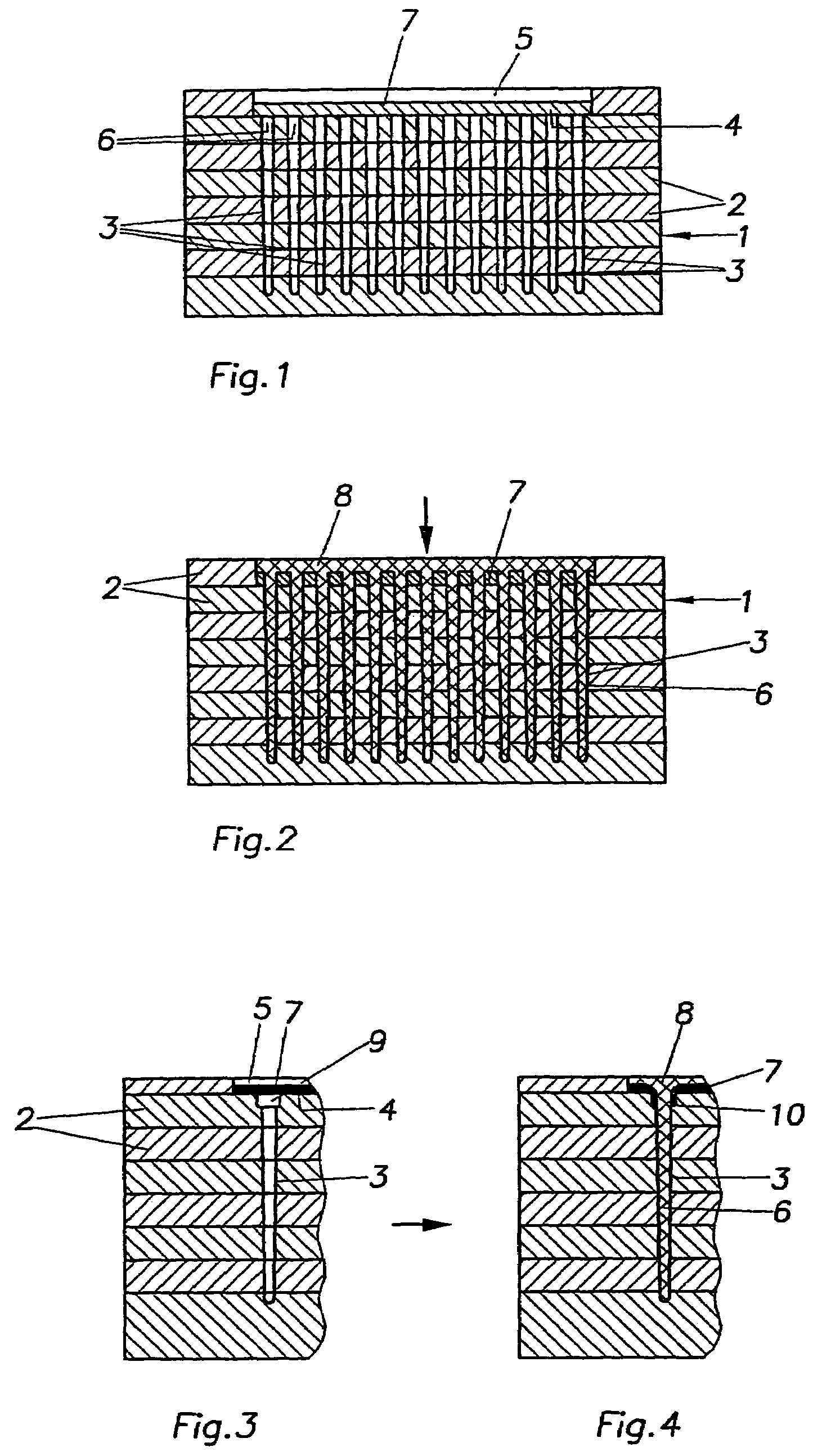
[0015]The method in accordance with the invention therefore utilizes an original carrier material that, in particular, does not exhibit openings, which must be aligned with the channels forming the bristles. On the contrary, the molding pressure is utilized to produce the through-holes having the required cross-section during the molding procedure itself in that the molding mass is injected through the carrier via the molding pressure. The material covering the free cross-section of the channels is thereby displaced in a sideward direction and also in the “shooting direction”. The hole pattern is only produced in the arrangement dictated by the channels and during formation of the bristles so that the problem of alignment of the holes with respect to the channels is avoided as is the problem of having one-to-one correspondence between the configuration of the holes and the channels so that expensive tools for producing a carrier having holes can be avoided.
[0020]In the above mentioned procedure, the molding of the molding mass can optionally be supported by the introduction of heat. This is particularly advantageous when the molding mass comprises reactive components such as duroplastics, in order to accelerate hardening and curing.
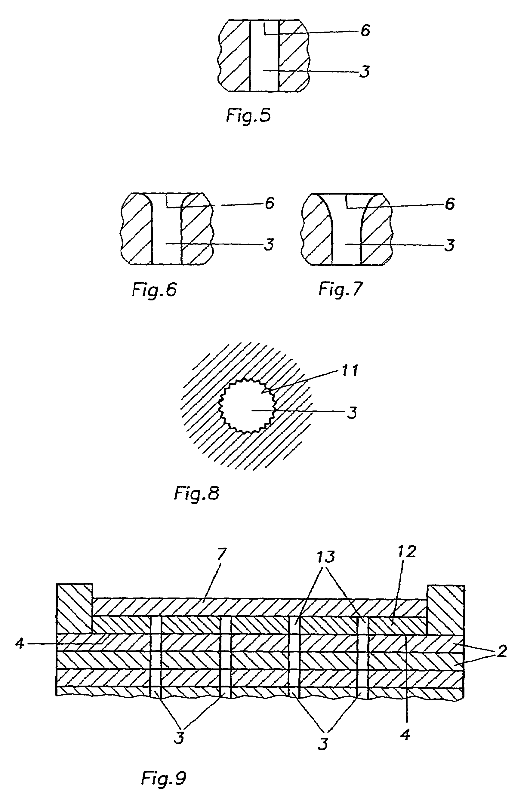
[0025]In order to prevent the formation of such a collar from weakening the cross-section of the bristle in the foot region, one can also provide the channels, which shape the bristles with an enlargement in the vicinity of their openings for acceptance of the carrier collar material. In this manner, the molecular structure of the bristle can develop in an unencumbered fashion and, in particular, the desired longitudinal molecular orientation of the bristles can be achieved.
[0027]Prior to disposition on the mold walls, the carrier is preferentially processed to effect weak material structures in the vicinities of the regions covering the openings to the channels. These could constitute simple thinning of the carrier, bottom holes or even symmetric, radially disposed intended breaking locations.
[0028]In one variation of the embodiment, an additional carrier can be inserted into the molding tool upstream of the channels, which has aligned holes, wherein the carrier which is to be penetrated by the molding mass can be disposed thereon to cover the holes of the additional carrier. In this particular case, the free cross-sections of the channels forming the bristles do not, in and of themselves, define “the perforation template” rather one has the additional influence of the holes of the additional carrier which lengthens the molding region. The carrier material that is displaced by the mold mass forming the bristles during penetration thereby is displaced into the holes of the additional carrier as a result of which a particularly good bandaging of the bristles in the bristle foot region is achieved.
[0044]The method in accordance with the invention always leads to individually standing bristles with close separations from each other in dependence on the configuration of the bristle forming channels. This bristle structure of individually standing bristles has turned out to be particularly advantageous for brushes and paintbrushes having stringent requirements with respect to hygiene, since soilage or media which are applied by the brush or the paintbrush do not accumulate between the bristles to the extent that they do with bristles bundles. Moreover, such bristles or brushes can be rinsed and cleaned in a straightforward and thorough fashion.

Problems solved by technology

Bristles of this type can, for practical reasons, only be utilized in limited applications e.g. for hair care or as throwaway brushes.
The reason for the deficient applicability and lack of acceptance is the fact that bristles which are injection molded have a fatigue strength under reverse bending stresses which is inadequate because, in contrast to bristles which are extracted from a spinning process, they do not have the molecular structure which is necessary for stability and which is primarily distinguished by a longitudinal orientation of the molecular chains, parallel to the bristle.
Moreover, these techniques require use of one and the same plastic for the working elements and for the carrier, which, for high quality plastics from which bristles having high quality requirements must be made, leads to corresponding increase in costs.
Nevertheless, the substantial disadvantages in applications remain in consequence of which these types of brushes are only suitable for limited applications.
Moreover, there is no possibility for adaptation of the material used for the carrier and the brushes in response to individual requirements or for differences among the bristles, in particular with regard to mechanical stability, material specific coefficients of friction, color etc.
Second of all, for injection molding technical reasons, the molding channels cannot be sufficiently narrow and deep in order to guarantee proper filling of the mold and as well as to facilitate removal from the mold.
Despite the fact that nylon would be theoretically appropriate to produce bristle-like properties, this does not occur, since a longitudinally oriented molecular structure cannot be effected, at least at the foot of the cleaning element due to the bulge.
As a result, the working elements become even more bulky.
Nevertheless, the production process is not suitable for bristle products having bristles of quality and application properties that are comparable to those of spin extruded bristles and certainly not better or improved with respect thereto.
Blockage effects and wall friction lead to an extensional flow having relatively large sheer forces proximate the walls at the “spinning nozzle” openings.
This root region is the most sensitive portion with respect to strength since the orientation of the molecules at this location is inadequate.
The previously mentioned procedure, due to the assignee, as well as the procedure in accordance with U.S. Pat. No. 2,621,369 have the disadvantage that the hole pattern in the prefabricated plastic carrier must identically match the predetermined grid defined by the channels in the molding tool.
In the event that this requirement is not precisely maintained, shifts occur in the region of the brush anchoring leading to an undesirable decrease in the cross-section at the foot of the bristle so that the bristle tears off or sheers off prematurely.
On the other hand, the bristle carrier having the predetermined holes and made from plastic can only be produced in a relatively economical fashion using the injection molding procedure.
However, injection molding nearly invariably leads to a shrinkage in the carrier not only due to the cooling process but also due to post-shrinkage over a subsequent extended period of time as a result of which the initial geometry is lost.
Moreover, one is restrained to use of low shrinkage plastics and is therefore substantially restricted with respect to the material combinations for the bristles and carrier.

Method used


Image

  • Method for the production of a bristle structure on a carrier
  • Method for the production of a bristle structure on a carrier
  • Method for the production of a bristle structure on a carrier

Examples


Embodiment Construction

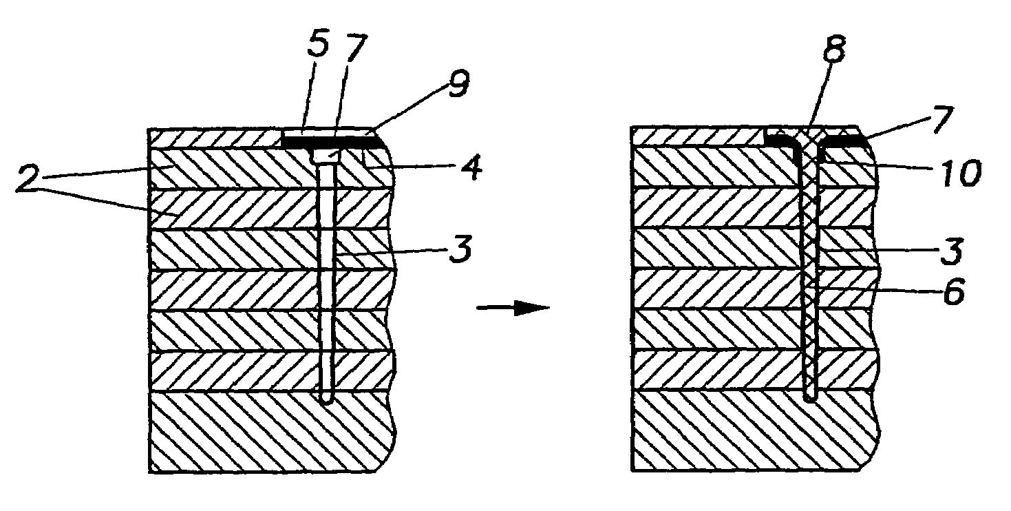
[0093]FIG. 1 schematically shows a molding tool 1, or a portion thereof, which is preferentially not of solid construction, rather is built up from parallel layered plates 2 whose purpose and action are described more closely in WO 02 / 03831 (DE 10033256 and DE 10130863) and in the unpublished patent applications DE 10301635.6 and DE 10212781.8, both due to the assignee of the instant application. The mold tool has a tool portion 1 having a plurality of preferentially parallel channels 3 in which the bristles are molded. The channels 3 extend from mold walls 4 and preferentially travel in a slightly conical fashion towards their closed ends. A carrier 7 is inserted into the mold cavity 5 onto the molding walls 4 and covers the free cross-section 6 of the molding channels 3.

[0094]The mold tool can be an injection molding, a pressure molding or a press-molding tool. The mold mass for the bristles is introduced into the mold cavity 5 with a sufficient amount of pressure to penetrate or ...


PUM

PropertyMeasurementUnit
Thicknessaaaaaaaaaa
Thicknessaaaaaaaaaa
Pressureaaaaaaaaaa

Abstract

A method for the production of bristles structures on an arbitrary kind of carrier using a mold tool is described having channels extending from channel walls for shaping bristles, wherein a mold mass for forming the bristles is introduced under pressure into the channels, preferentially using the injection molding technique. Towards this end, the carrier is disposed directly or indirectly onto the mold walls of the channels in such a fashion that the free cross-section of the channels is completely covered and the mold mass is subsequently introduced onto the carrier with a sufficient mold pressure (injection pressure) that the carrier is broken-through in the vicinity of the free cross-section of the channels thereby displacing the carrier material, with the carrier mass subsequently filling the channels.

Description

[0001]This application is the national stage of PCT / EP03 / 04938 filed on May 12, 2003 and also claims Paris Convention priority of DE 102 21 869.2 filed May 15, 2002.BACKGROUND OF THE INVENTION[0002]The invention concerns a method for manufacturing a bristle structure on an arbitrary kind of carrier using a molding tool having channels, extending from a mold wall, for the molding of bristles, wherein a mold mass for forming the bristles is introduced into the channels under pressure.[0003]Bristle products which include, in particular, brushes of every kind, paint brushes as well as brooms are predominantly produced using mechanical methods with which the bristle carrier is initially made having holes and the bristle bundles are mechanically inserted at a subsequent time. With the advent of plastics the brush bodies are manufactured through injection molding or molding processes and the bristles are attached either in the conventional mechanical fashion or, recently, using thermal tec...

Claims


Application Information

Patent Timeline
IPC IPC(8): B29C45/14B29C45/16B29C45/17
CPCB29C45/14344B29C45/14795B29C45/1418B29L2031/425B29C45/1704B29C2045/14983B29L2031/42B29C45/1642B29C45/14B29C45/26A46D3/00
Inventor WEIHRAUCH, GEORG
Owner GEKA
Learn More