
Audio speaker with wobble free voice coil movement

Inactive Publication Date: 2007-06-05
EARTHQUAKE SOUND
View PDF25 Cites 13 Cited by
  • Summary
  • Abstract
  • Description
  • Claims
  • Application Information

AI Technical Summary

Benefits of technology

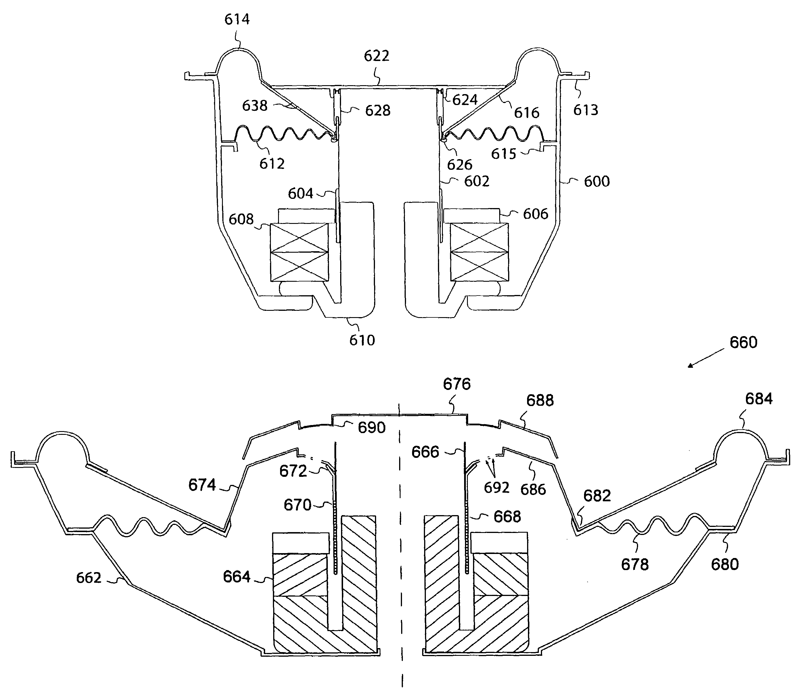
[0021]An aspect of the present invention provides an embodiment that provides a symmetrically loaded, shallow suspension speaker. In the speaker embodiments of the present invention, the symmetrically loaded, shallow suspension supports a substantially stiff diaphragm that functions similarly to the “cone” of the prior art. In the present invention the diaphragm, or cone, is made of a material such as honeycomb, thin aluminum, and other composite and non-composite light-weight materials; conventional cone materials will not work in this application since the diaphragm is substantially flat and light-weight. This flat diaphragm is suspended by the outermost edge with a suspension system that is entirely outside the diameter of the magnet, thus allowing the suspension to extend to nearly the bottom of the speaker basket on the maximum inward excursion of the voice coil and diaphragm. Thus, the suspension operational depth is not the limiting factor of the speaker basket design and the actual mounting depth of the speaker. Note that mounting depth and cone wobble control are interrelated in the speakers of the present invention; the closer the outer portion of the suspension is to an inner one, the chance of wobble increases as the the mounting depth of the speaker becomes shallower. As will be seen below in the detailed description of the various embodiments of the present invention, the elements of the suspension system of the present invention have been designed maximize the spacing between the inner and outer portions of the suspension system, thus minimizing the possibility of wobble in the low profile speakers of the present invention.
[0022]The various embodiments of the present invention permit the designer to maximize air movement in a given mounting depth with a configuration that optimizes the operation of the moving parts (i.e., diaphragm, suspension and voice coil) in the electromagnetic environment that complements the fixed mechanical structural configuration of the non-moving parts. In one embodiment, this invention allows the designer to have an over excursion (outward / inward limiter) that is optimized with the available mounting depth. For example, the present invention allows the designer to have a 15″ diameter speaker that fits in a mounting depth of as little as 3.5″ with a diaphragm excursion of approximately ±1″, while a conventional speaker with the same size working piston requires a mounting depth of 6″ to 7″.
[0024]Yet another embodiment of the present invention provides a speaker that is designed to substantially eliminate wobble of the voice coil during operation, and thus remove that source of distortion and early failure of the speaker. This is accomplished with the creation of triangular ring that extends upward from the top edge of the voice coil bobbin with that ring mating with a flat diaphragm at a right angle directly above the top edge of the bobbin. The outer edge of the diaphragm connects to the inner edge of the surround at the point where a sloping side of the “triangle” is also connected and slopes down to the top edge of the bobbin where the opposite end is connected. The outer portion of the diaphragm provides the third side of the triangle.

Problems solved by technology

At low frequencies, the use of open ports, or open ports and tubes, in the speaker cabinet becomes unmanageable because of the large air mass that needs to be moved to provide adequate tuning.
This imbalance is indicative of the relative distortion that can be heard as the loudness of the passive radiator nosedives and falls below an audible loudness.
At low frequencies, a limitation of passive radiators has been that the low frequencies require large displacements of the moveable radiator elements.
Such large displacements can exceed the available range of motion of moveable radiator elements.
The sudden stop in the movement of the spider, due to its full extensions, causes distortions in adjacent components as well as in the pressure gradients in the speaker chamber.
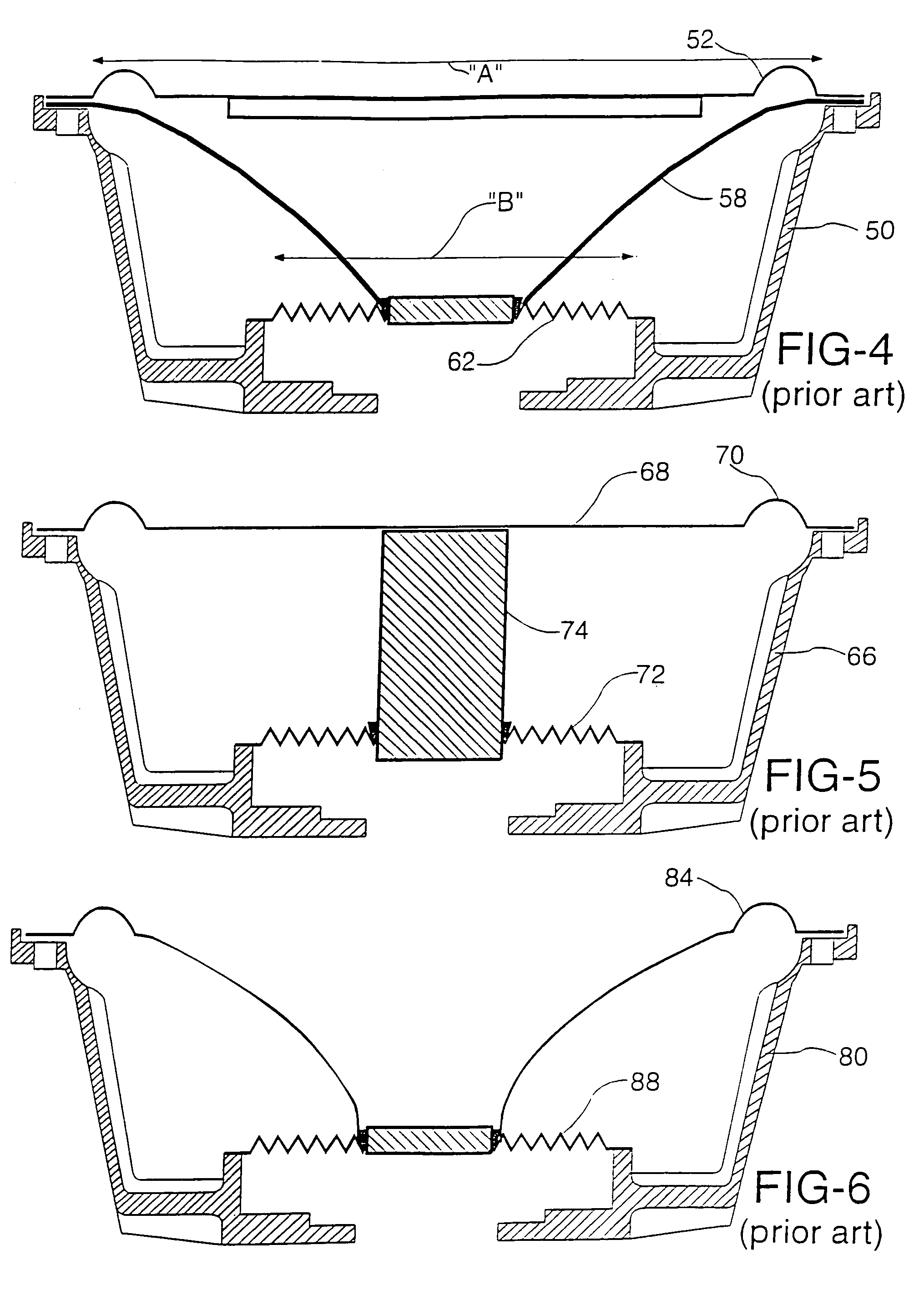
However, the use of a surround around the perimeter of the top of the cone and the cone shape produces cone wobble which also distorts the sound.
The spatial requirement of the prior art passive radiators is also a drawback.
The prior art passive radiators are quite large and bulky and extend a large distance into any sealed cavity.
Conventional speakers require a huge mounting depth that render them useless in shallow spaces where consumers now wish to place speakers.
Hence conventional speakers clearly will not fit in shallow spaces, such as walls where the mounting depth is limited to about 3.5″, or less, unless a smaller diameter conventional speaker is used.
Thus, consumer demand has created a need that conventional speakers can not meet and still provide the performance desired by the consumer.
Conventional speakers have many weaknesses that have become much more evident in longer stroke woofers.
Additionally, the structure of conventional speakers promotes harmonically related bending of the cone during inward / outward strokes that fatigues the inner portion of the cone and leads into what is known as a neck-cone failure.
Prior to that type of failure the cone is known to have a cycle per life during which the cone is breaking down and during the slow breakdown of the cone, the conventional promotes increasing distortion that is increasingly unpleasant for the listener.
Further conventional speakers have not been designed to maintain the inner suspension (spider) parallel to the outer suspension (surround) as the cone is driven by the voice coil.
Another problem that results in reduced audio performance of conventional speakers is wobble of the voice coil during operation of the speaker.
Current speaker design structures suffer from several compromising parts that play a major role in producing a high level of harmonic distortion.
The combination of these offsets leads to wobble of the voice coil bobbin.
Wobble can also reduce the useful life of a speaker by repeatedly over stressing the cone and other components that eventually results in failure of the component, e.g., a crack or a tear in the cone, partial separation of the cone and surround, etc.
Wobble can even result in total failure of the speaker.

Method used


Image

  • Audio speaker with wobble free voice coil movement
  • Audio speaker with wobble free voice coil movement
  • Audio speaker with wobble free voice coil movement

Examples


first embodiment

[0117]FIG. 36 show a first embodiment low profile, overhung, shallow speaker design with FIG. 36A in the unexcited position, FIG. 36B in the maximum outward excursion position, and FIG. 36C in the maximum inward excursion position. Included is a low profile frame or basket 402 that mounts to baffle board 400 in the installed location. Basket 402 has a bottom thickness of “H”. In the bottom center of basket 402 is a typical overhung magnet / voice coil audio motor with an upwardly extending steel doughnut with an outwardly extending flange 410 with that flange having a thickness of “T”. Mounted on the flange of doughnut 410 is a circular magnet 406 having a center hole that has a larger diameter than the diameter of the upwardly extending portion of the doughnut. Magnet 406 has a thickness of 2α. On top of magnet 406 is a steel ring 408 having outer and inner diameters that are approximately the same as those diameters of magnet 406. Ring 408 also has a thickness “T”.

[0118]Additionally...

second embodiment

[0123]FIG. 39 shows an overhung, low profile speaker that is similar to that of FIG. 36A, the difference being that surrounds 418 and 420 have been replaced with a single bladder 422. In construction, bladder 422 is similar to a bicycle tube with the outer most side connected to inside top edge of basket 402 and an opposite side connected to the bottom of the outer most leg of the “V” shaped edge of diaphragm 404. Mounted in that way, a portion of bladder 422 extends upward like surround 418 while another portion extends downward into basket 420 like surround 420. In operation, bladder 422 performs similarly to the combination of surrounds 418 and 420 as discussed above in relation to FIGS. 36A, 36B and 36C.

[0124]By connecting the outer most side of bladder 422 to a lower point within basket 402 that is approximately horizontally even with the underside of the outer most leg of the “V” shaped edge of the diaphragm rocking of the diaphragm during speaker operation is minimized. Bladd...

fourth embodiment

[0126]FIG. 37 show an overhung, low profile speaker of the present invention. This embodiment, as will be seen, has built in stops that define the maximum Inward and outward travel of the diaphragm. Included in this embodiment is a speaker basket 402′ with an outwardly extending upper flange that mounts to baffle board 400 of the mounting location of the speaker. Basket 402′ has a bottom thickness “H”. Mounted centrally within basket 402′ is a post 428 having a threaded upper end 430 with the overall height of post 428 being less than the height of basket 402′ from the bottom to the mounting flange. Also induded is steel ring 408 magnetically adhering to the bottom of circular magnet 406 which in turn magnetically adheres to the flange of circular steel doughnut 410′ with a hole therethmugh that is tapped at the upper end. The flange of doughnut 410′ and ring 408 each have a thickness “T”, and magnet 406 has a thickness 2α′ (note the distance α′ in this figure is not necessarily the...


PUM


Abstract

A speaker that is designed to substantially eliminate wobble of the voice coil during operation, and thus remove that source of distortion and early failure of the speaker. This is accomplished with the creation of triangular ring that extends upward from the top edge of the voice coil bobbin with that ring mating with a flat diaphragm at a right angle directly above the top edge of the bobbin. The outer edge of the diaphragm connects to the inner edge of the surround at the point where a sloping side of the “triangle” is also connected and slopes down to the top edge of the bobbin where the opposite end is connected. The outer portion of the diaphragm provides the third side of the triangle.

Description

CROSS-REFERENCE[0001]This application is a Continuation-In-Part of application Ser. No. 10 / 058,868, filed Jan. 28, 2002 (now U.S. Pat. No. 6,675,931, issued Jan. 13, 2004), which is a Continuation-In-Part application Ser. No. 09 / 542,155, filed Apr. 4, 2000 (now U.S. Pat. No. 6,460,651, issued Oct. 8, 2002), which is a Continuation In Part application of application Ser. No. 09 / 201,398, filed Nov. 30, 1998 (now U.S. Pat. No. 6,044,925 issued Apr. 4, 2000).BACKGROUND OF THE INVENTION[0002]1. Field of the Invention[0003]This invention relates to loud speakers and in particular to the construction of audio speakers that have virtually no wobble of the voice coil bobbin during operation.[0004]2. Description of the Related Art[0005]A goal of sound reproduction equipment is to provide a life-like sound quality to the listener. Lifelike sound quality is understood to be best achieved when a sound system including the speakers have a flat frequency response curve throughout the range of soun...

Claims


Application Information

Patent Timeline
IPC IPC(8): H04R7/12H04R7/22H04R9/04H04R9/06G10K13/00H04R9/02H04R1/28
CPCH04R7/20H04R9/045H04R1/2834H04R7/06H04R9/025H04R9/06H04R31/006G10K13/00
Inventor SAHYOUN, JOSEPH YAACOUB
Owner EARTHQUAKE SOUND
Learn More