Edge bending apparatus

a technology of edge bending and bending shaft, which is applied in the direction of forging/pressing/hammering apparatus, metal-working feeding device, forging press, etc., can solve the problems of affecting the finishing accuracy of products, too much looseness or play between the component parts, and wear of the pivot shaft with long time use, so as to achieve easy transfer and reduce size and cost

Inactive Publication Date: 2007-05-29
HONDA MOTOR CO LTD
View PDF23 Cites 3 Cited by
  • Summary
  • Abstract
  • Description
  • Claims
  • Application Information

AI Technical Summary

Benefits of technology

[0016]According to the present invention, the workpiece is placed directly on the upper molds with no intervening cam and cam driver. Thus, there is no need to worry about occurrence of undue looseness or play between the elements, and it is possible to maintain a good finishing accuracy of products over a long period of time.
[0017]In addition, because no intervening cam and cam driver is employed, the edge bending apparatus can be greatly simplified in construction.
[0020]According to the present invention, the workpiece is placed directly on the upper molds with no intervening cam and cam driver. Thus, there is no need to worry about occurrence of undue looseness or play between the elements, and it is possible to maintain a good finishing accuracy of products over a long period of time.
[0021]In addition, because no intervening cam and cam driver is employed, the edge bending apparatus can be greatly simplified in construction.
[0024]Further, in the present invention, the first, second and intermediate workpiece transfer sections each include rollers provided to project above an upper surface thereof in such a manner that the workpiece can be easily transferred horizontally on the rollers through manual operation by a human operator.
[0025]Although the first, second and intermediate workpiece transfer sections may be driven using a motor or cylinder as a driving source to horizontally transfer the workpiece, the present invention is arranged to horizontally transfer the workpiece by placing the workpiece on the rollers, provided to project above the upper surface of the workpiece transfer sections, so that the workpiece can be easily transferred manually by a human operator. Thus, the first, second and intermediate workpiece transfer sections can be considerably reduced in size and cost.

Problems solved by technology

Further, with the hemming technique disclosed in the ② publication, the pivot shaft 11 wears with long time use, as a result of which too much looseness or play would be produced between the component parts.
Thus, the pre-hemming punch 9 tends to be positioned inaccurately, which would adversely affect the finishing accuracy of products.

Method used


Image

  • Edge bending apparatus
  • Edge bending apparatus
  • Edge bending apparatus

Examples


Embodiment Construction

[0043]Now, a detailed description will be made about embodiments of the present invention, with reference to the accompanying drawings.

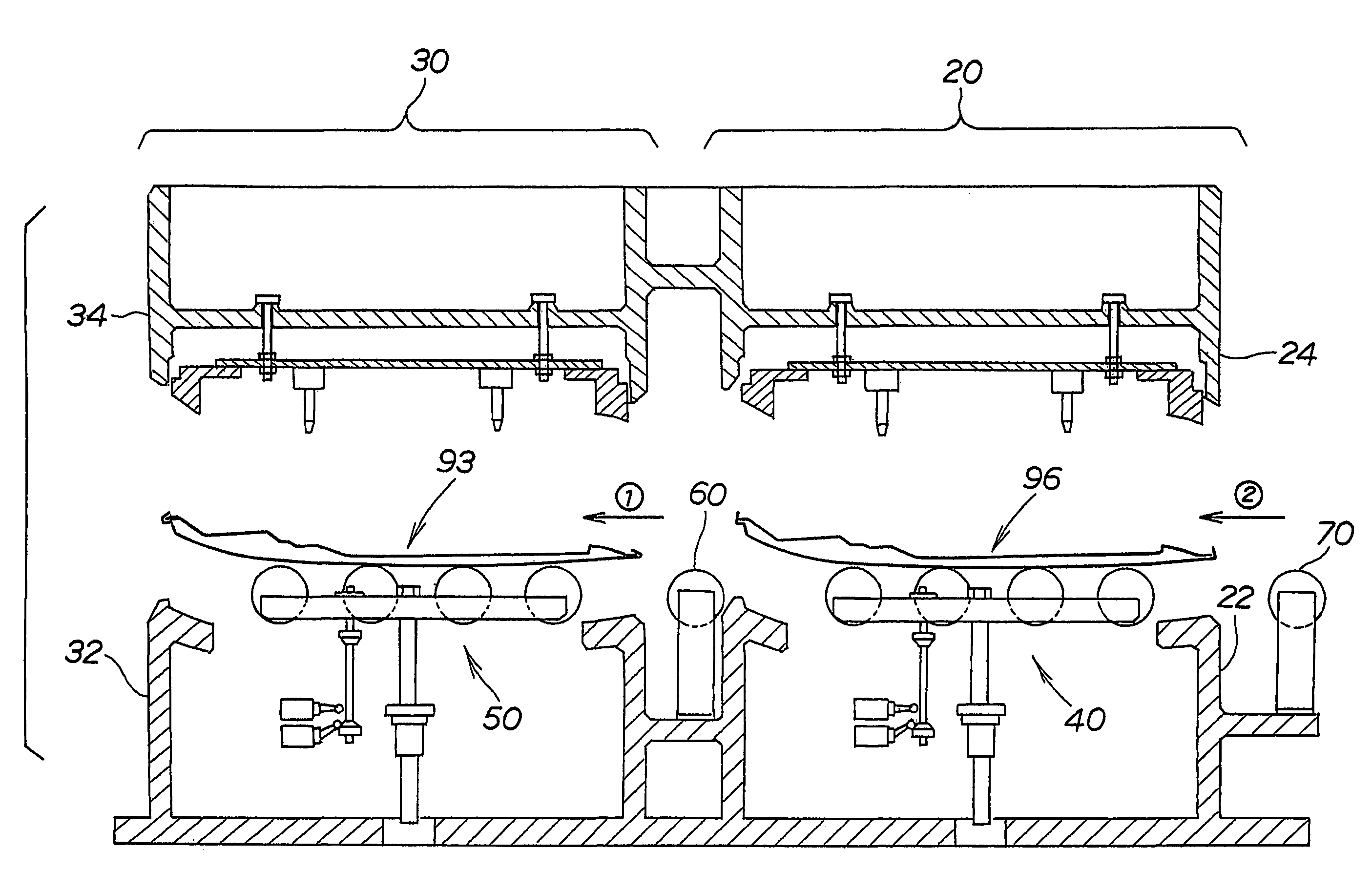
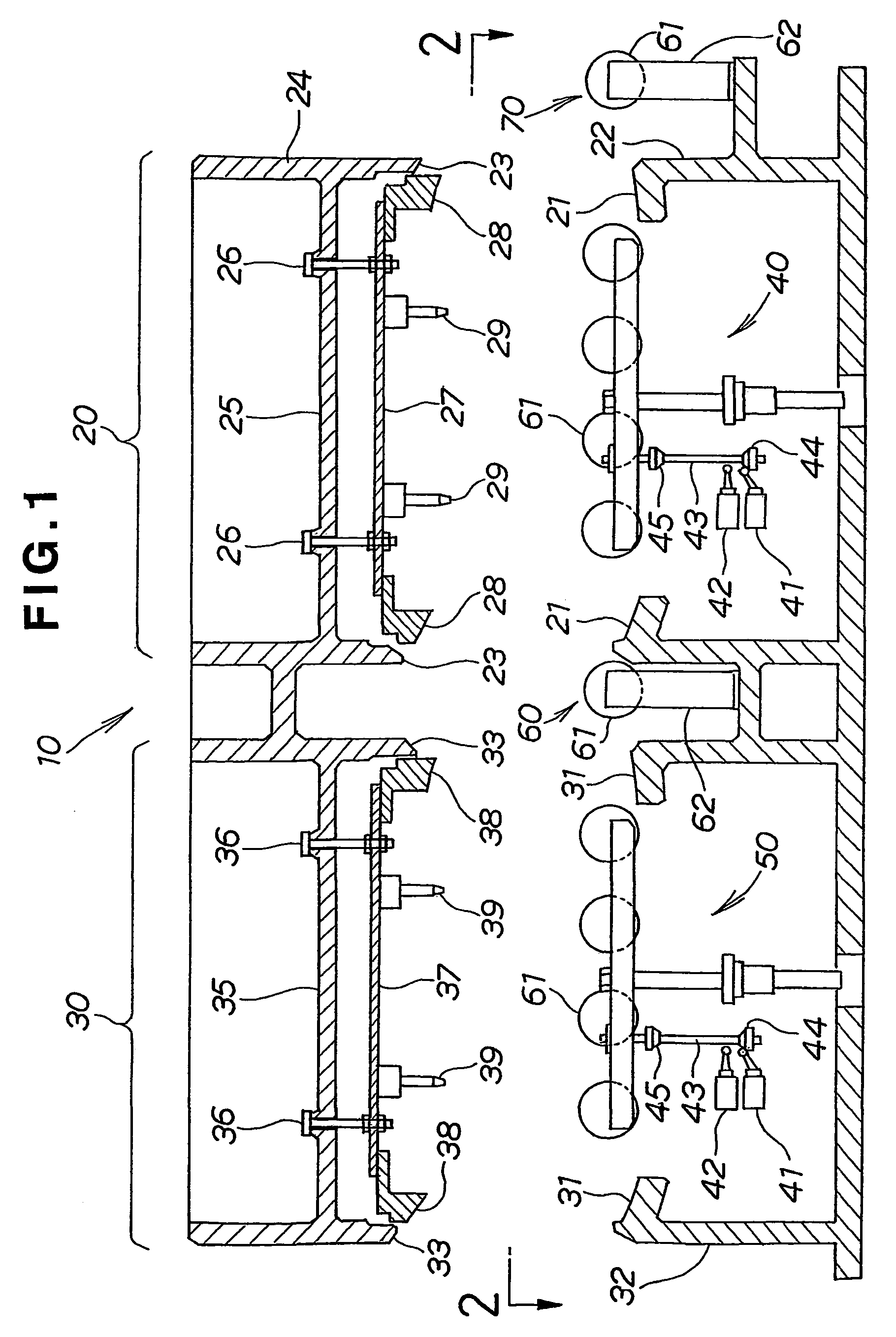
[0044]FIG. 1 is a sectional view of an edge bending apparatus in accordance with the present invention. The edge bending apparatus 10 generally comprises first and second hemming mold units 20 and 30 integrally connected with each other in a left-and-right (horizontal) direction of the figure. Specifically, the first hemming mold unit 20 includes a first lower mold 22 having a peripheral support surface 21 for supporting thereon a peripheral edge of a workpiece (not shown in the figure), and a first upper mold 24 vertically movable toward and away from the first lower mold 22 and having a bending blade 23 for bending the peripheral edge of the workpiece to halfway through a predetermined full bending angle. The first hemming mold unit 20 also includes a hanging frame 27 attached, via bolts 26, to a cross beam 25 of the first upper mold 24 in such a m...


PUM

PropertyMeasurementUnit
bending angleaaaaaaaaaa
halfway angleaaaaaaaaaa
shapeaaaaaaaaaa

Abstract

A first hemming mold unit (20) and a second hemming mold unit (30), are installed in a single pressing machine. The first hemming mold unit (20) performs partial bending of an edge (95) of a workpiece (93; 96). The workpiece (93; 96), having undergone the partial bending, is transferred to the second hemming mold unit (30), the second hemming mold unit (30) performs remaining necessary bending of the edge of the workpiece (93; 96). Here, predetermined bending of the edge (95) of the workpiece (93; 96) can be completed within the single pressing machine only by downward movement of upper molds (24, 34) of the first and second hemming mold units (20, 30), without having to use a cam and cam driver.

Description

TECHNICAL FIELD[0001]The present invention relates an edge bending technique suitable for use in manufacture of vehicle hoods.BACKGROUND ART[0002]Edge bending is an essential technique for the manufacture of automobiles, particularly their bonnets or hoods. A typical example of such hoods is shown in top plan in FIG. 14 hereof. The example hood has a cross section as shown in FIG. 15 hereof.[0003]As shown in FIG. 14, the hood 100 includes a stiffener member 101 covered with a skin member 102, and edges of the skin member 102 are folded back around edges of the stiffener member 101 so that the skin member 102 and stiffener member 101 are secured with each other into an integral unit.[0004]Discussion will be made next as to typical steps in a conventional method of manufacture of the hood 100 with reference to (a) to (c) of FIG. 16 hereof.[0005]In a first step shown in section (a) of FIG. 16, there are first provided a skin member 102 having been formed by bending or drawing a blank i...

Claims


Application Information

Patent Timeline
Patent Type & Authority Patents(United States)
IPC IPC(8): B23P19/00B21D39/00B23P11/00B21D19/08B21D39/02B21D43/00
CPCB21D39/021Y10T29/53422Y10T29/49915
Inventor BABA, KOUSEIUSUI, TOSHIYUKI
Owner HONDA MOTOR CO LTD
Why Eureka
Try Eureka