
Tunable dispersion compensator

a compensator and dispersion technology, applied in the field of dispersion compensation, can solve the problems of no adjustment mechanism, no optimal fix, and dispersion compensator

Inactive Publication Date: 2007-05-22
AEGIS SEMICON
View PDF95 Cites 62 Cited by
  • Summary
  • Abstract
  • Description
  • Claims
  • Application Information

AI Technical Summary

Problems solved by technology

The problem to be addressed relates to fiber optic communication systems used to transport digital data and more specifically to chromatic dispersion in such systems.
This is not an optimum fix, however.
In addition, there is no mechanism to adjust it short of uninstalling it.
No known tunable dispersion compensator, whether based on fiber gratings, etalons, waveguides, free space optics or other techniques is as yet fully satisfactory for industry requirements.

Method used


Image

  • Tunable dispersion compensator
  • Tunable dispersion compensator
  • Tunable dispersion compensator

Examples


Embodiment Construction

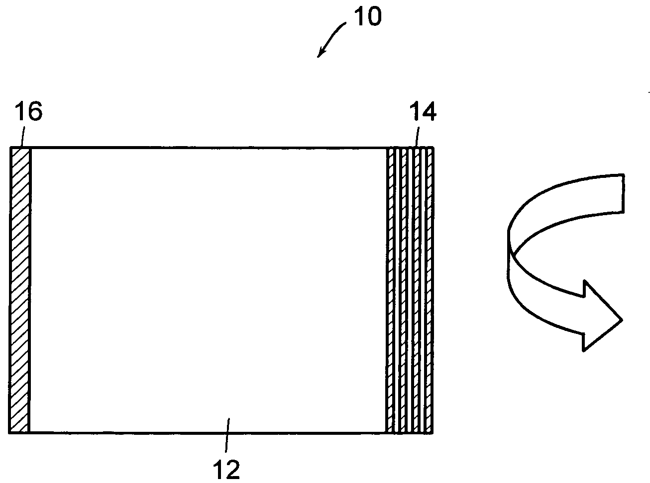
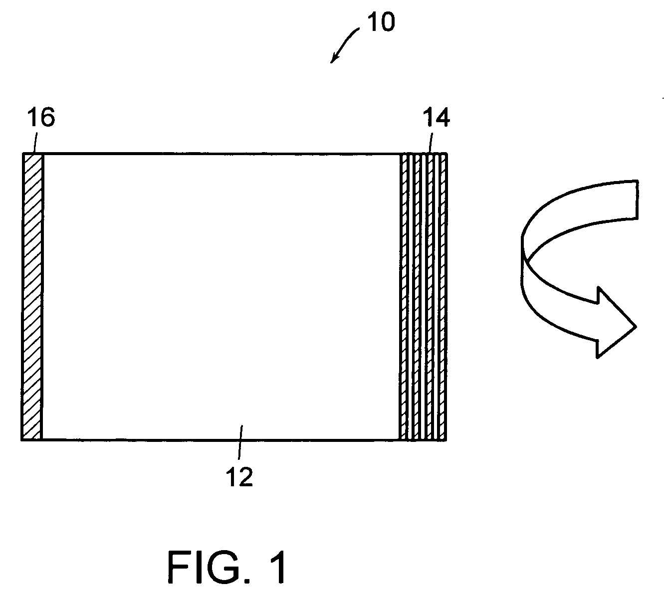
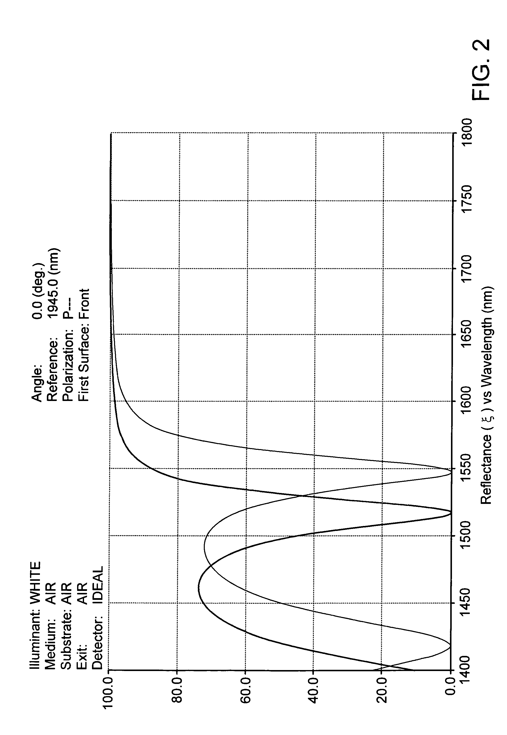
[0026]FIG. 1 shows a Gires-Tournois (GTI) etalon 10 which includes a silica spacer 12 with a thermo-optically tunable thin film reflective structure 12 on one side and a highly reflecting mirror 14 on the opposite side. The thermo-optically tunable thin film reflective structure, which is described in greater detail later, is basically a multi-layer thin film interference structure which functions as a partially reflecting mirror. By itself, it exhibits a reflectivity which varies as a function of wavelength. Varying the temperature of this thin film interference structure shifts the spectral reflectivity curve as a function of the temperature of the film. When viewed from the point of view of a particular fixed wavelength of operation, this amounts to an adjustable reflectivity. Hence, when used as the front mirror in a GTI, the thermo-optically tunable thin film filter produces a tunable pulse delay and tunable dispersion.

[0027]A Fabry-Perot etalon, in contrast to the GTI interfer...


PUM

PropertyMeasurementUnit
timeaaaaaaaaaa
frequenciesaaaaaaaaaa
thickaaaaaaaaaa

Abstract

An optical dispersion compensator including: a spacer element having a top surface and a bottom surface; a thin film, multi-layer mirror formed on the top surface of the spacer element, the thin film mirror having a thermally tunable reflectivity; a highly reflective mirror element formed on the bottom surface of the spacer element; and a heater element for controlling a temperature of the thermally tunable thin film mirror.

Description

[0001]This application claims the benefit of U.S. Provisional Application No. 60 / 501,154, filed Sep. 8, 2003, and U.S. Provisional Application No. 60 / 519,249, filed Nov. 12, 2003.TECHNICAL FIELD[0002]This invention relates to dispersion compensation.BACKGROUND OF THE INVENTION[0003]The problem to be addressed relates to fiber optic communication systems used to transport digital data and more specifically to chromatic dispersion in such systems. Chromatic dispersion is the process by which an optical pulse spreads out as it propagates in any medium which does not have absolutely constant speed of light vs. wavelength. An optical fiber is such a medium and devices such as thin film filters or optical amplifiers also contribute to dispersion.[0004]For example, at a 10 GHz data rate, a “1” pulse representing the digital “1” is about 100 ps duration in time or 3 cm long in space. The basics of Fourier analysis show that a laser signal modulated to carry such pulses is no longer a single...

Claims


Application Information

Patent Timeline
Patent Type & Authority Patents(United States)
IPC IPC(8): G02B6/26G02B6/42G02F1/19H04B10/18G02B6/293G02B6/32G02B6/34
CPCG02B6/29358G02B6/29361G02B6/29394G02B6/29395G02B6/29398G02B6/32H01L2224/48091H01L2224/73265H01L2924/00014H01L2924/10253H01L2924/00
Inventor DOMASH, LAWRENCE H.WAGNER, MATTHIAS
Owner AEGIS SEMICON
Learn More