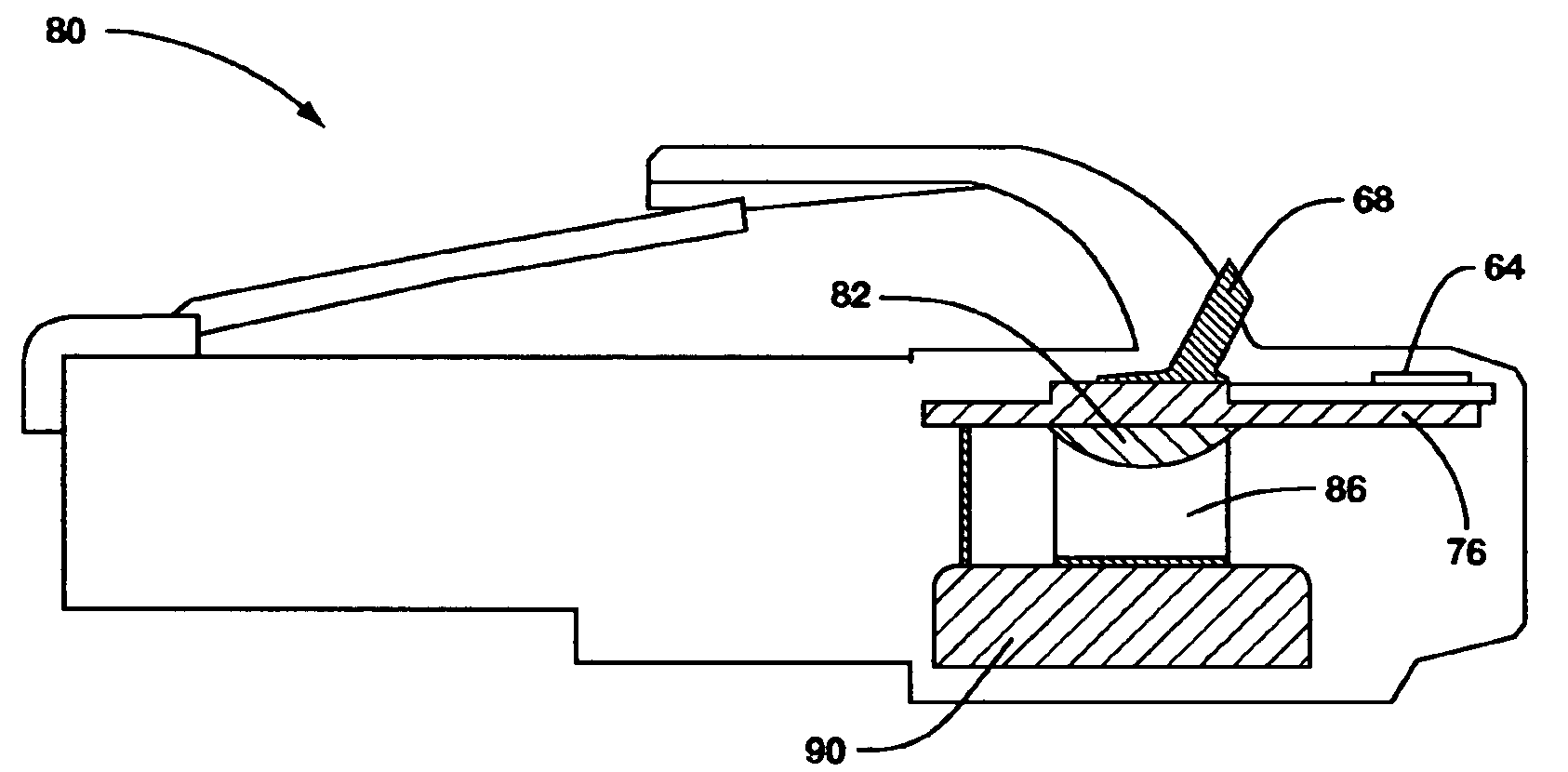
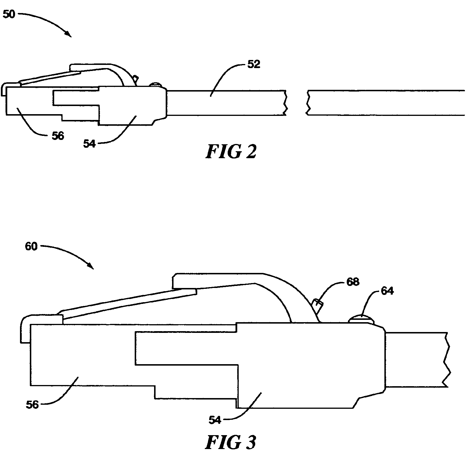
Networking cable tracer system
a tracer system and network cable technology, applied in the field of network cable tracer system, can solve the problems of increased service costs, increased cost, and substantial length of network cables, and achieve the effect of low cost and simple us
- Summary
- Abstract
- Description
- Claims
- Application Information
AI Technical Summary
Benefits of technology
Problems solved by technology
Method used
Image
Examples
Embodiment Construction
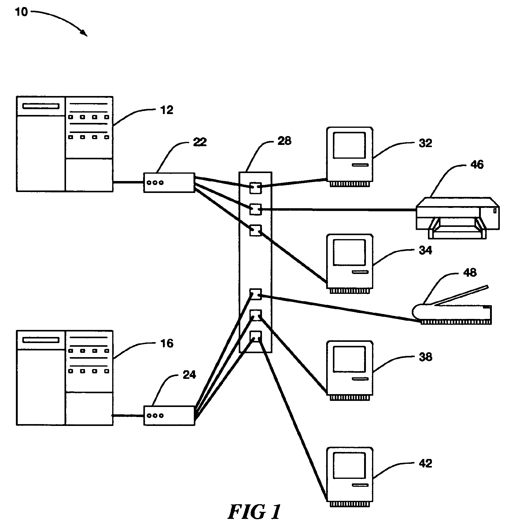
[0024]FIG. 1, shown generally by the numeral 10, illustrates, by way of background, a typical networked environment that includes servers, computers, hubs, peripheral devices, and a cable panel.
[0025]In this example computers 32, 34, 38, and 42 are each connected by networking cables to a cable panel 28. The computers can be at multiple locations. Also attached to panel 28 by networking cable are peripheral devices such as printer 46 and scanner 48. Panel 28 is often located at a central room where service personnel can access it. From panel 28 multiple computers and peripheral devices are often then linked by networked cables to hubs such as 22 and 24, which then are connected to servers such as 12 and 16. Typically, one room may house multiple servers and hubs. Various protocols are used to support data transfer between computer and server pairs. A typical protocol is Ethernet.
[0026]The example shown is a small network and typical networks are much larger. In addition to the devic...
PUM
 Abstract
Description
Claims
Application Information
 - R&D
- Intellectual Property
- Life Sciences
- Materials
- Tech Scout
- Unparalleled Data Quality
- Higher Quality Content
- 60% Fewer Hallucinations
Browse by: Latest US Patents, China's latest patents, Technical Efficacy Thesaurus, Application Domain, Technology Topic, Popular Technical Reports.
© 2025 PatSnap. All rights reserved.Legal|Privacy policy|Modern Slavery Act Transparency Statement|Sitemap|About US| Contact US: help@patsnap.com


