
In-line multicylinder combustion engine

a multi-cylinder combustion engine and combustion engine technology, which is applied in the direction of engines/engines, machines/engines, cycles, etc., can solve the problems of difficult to achieve a relatively large banking angle of the motorcycle frame structure, increase the size of the cylinder bore, and increase the total so as to achieve a large banking angle and reduce the length and width of the combustion engine. , the effect of reducing the length

Inactive Publication Date: 2007-05-22
KAWASAKI HEAVY IND LTD
View PDF8 Cites 12 Cited by
  • Summary
  • Abstract
  • Description
  • Claims
  • Application Information

AI Technical Summary

Benefits of technology

This configuration enables a larger banking angle, reduces the engine's size, and positions the center of gravity lower, enhancing the motorcycle's performance by minimizing component count and weight, while allowing for increased cylinder bore diameter for higher output.

Problems solved by technology

However, the larger the cylinder bore, the greater the total width of the combustion engine.
Accordingly, considering also that the electric generator is disposed on one end of the crankshaft as discussed above, it is difficult to obtain a relatively large banking angle of the motorcycle frame structure.
As a result thereof, increase of the size of the cylinder bores is difficult to achieve.
However, where the crankshaft is arranged in line with input and output shafts as shown in FIG. 1 of the above discussed patent publication, it has been found that not only does the front-to-rear length or the longitudinal dimension of the combustion engine become great along with increase in weight thereof, but a wheelbase of the motorcycle also increases, resulting in an undesirable increase of the size and weight of the motorcycle.
With this design, setteing the center of gravity of the combustion engine at a lower position is difficult to achieve.

Method used


Image

  • In-line multicylinder combustion engine
  • In-line multicylinder combustion engine
  • In-line multicylinder combustion engine

Examples


Embodiment Construction

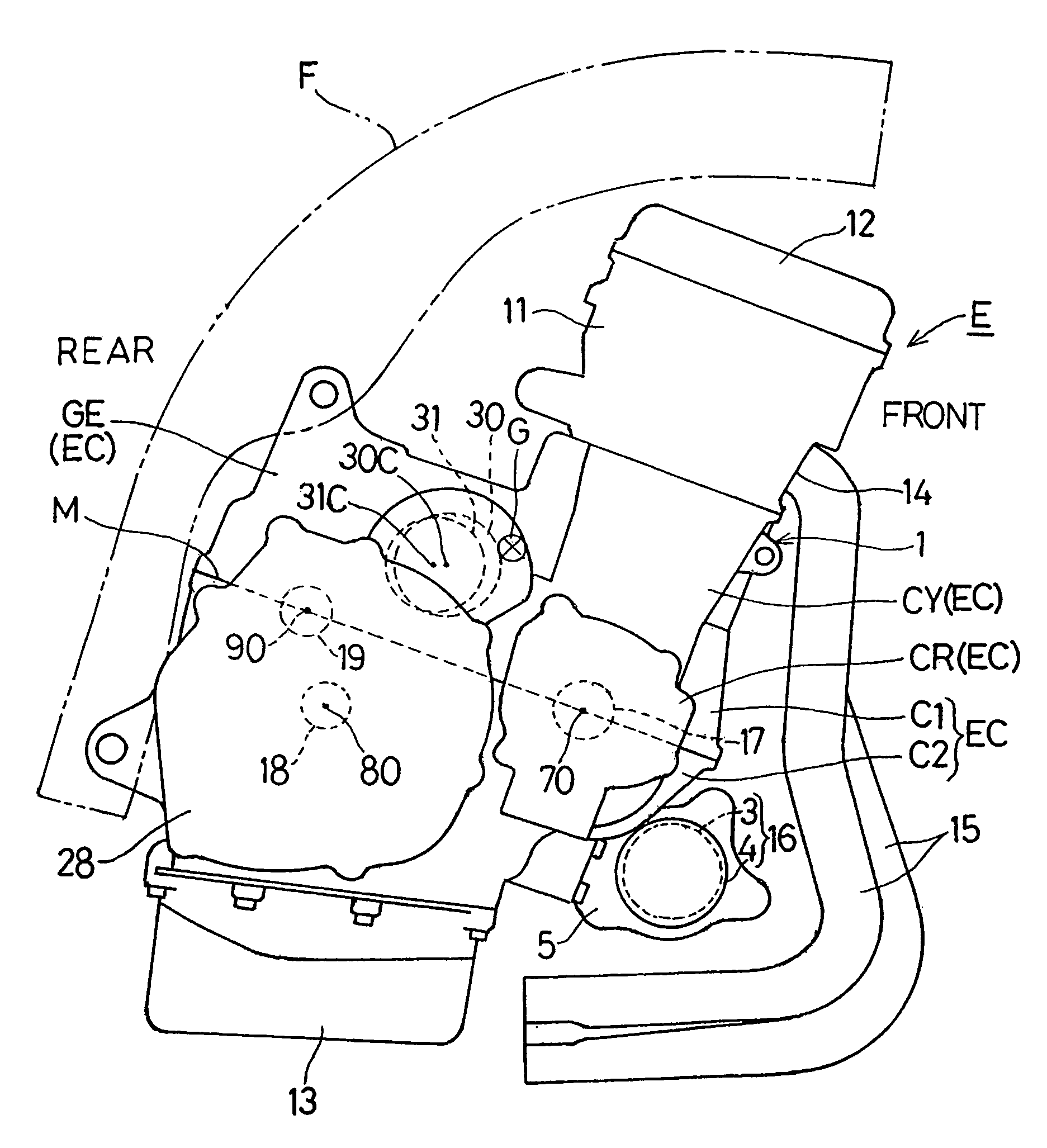
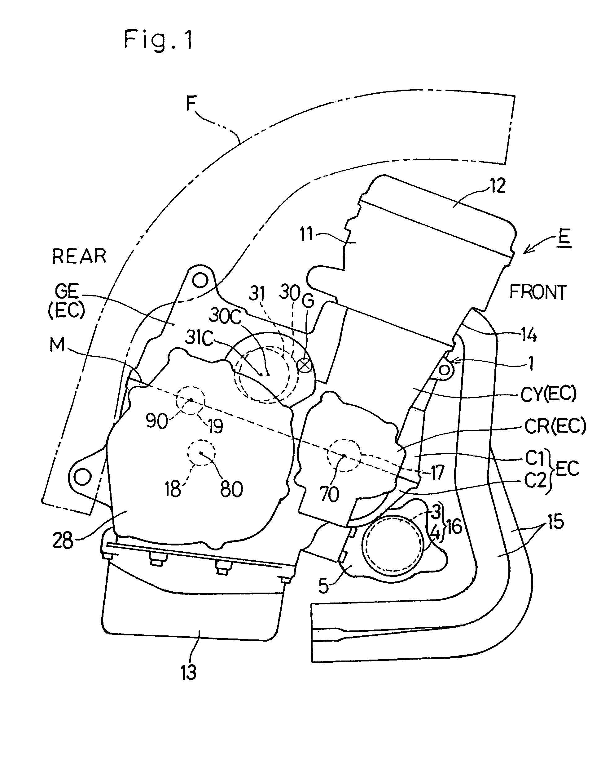
[0029]Hereinafter, a preferred embodiment of an in-line multicylinder internal combustion engine for a motorcycle in accordance with the present invention will be described in detail with reference to the accompanying drawings. Referring to FIG. 1 showing a side view of the in-line multicylinder internal combustion engine E for the motorcycle in accordance with one preferred embodiment of the present invention, the combustion engine E is an in-line four-cylinder, four-cycle engine and is mounted on a front lower portion of a motorcycle frame structure F. This motorcycle combustion engine E includes an engine body 1. The engine body 1 includes an engine casing EC made up of a crankcase CR, a cylinder block CY and a gear case GE. The engine casing EC is of a two-piece construction including an upper casing component C1 and a lower casing component C2. The cylinder block CY, an upper half portion of the crankcase CR and an upper half portion of the gear case GE are integrally formed in...


PUM


Abstract

There is provided an in-line multicylinder combustion engine of a type, in which the length and the width of the combustion engine can be reduced; which can be assembled compact in size with its center of gravity lowered in position; in which mass centering in the combustion engine can be accomplished, The engine (E) includes a crankshaft (17), an input shaft (18) and an output shaft (19). The crankshaft (17) is connected with the input shaft (18) through a clutch gear (40). An imaginary plane (H) containing respective axes (70, 80) of the crankshaft (17) and the input shaft (18) lies substantially horizontally, while the axis (90) of the output shaft (19) is positioned above the imaginary plane (H). An electric generator (30) having a drive gear (52) is positioned adjacent the center of gravity (G) defined between the crankshaft (17) and the output shaft (19), with its generator longitudinal axis (30C) positioned above another imaginary plane (M) connecting between the respective axes (70, 90) of the crankshaft (17) and the output shaft (19). The drive gear (52) of the electric generator (30) is meshed with the clutch gear (40).

Description

BACKGROUND OF THE INVENTION[0001]1. Field of the Invention[0002]The present invention generally relates to an in-line multicylinder combustion engine for use primarily in motorcycles and, more particularly, to provide the in-line multicylinder combustion engine of a kind that is assembled compact in size with its center of gravity lowered and that a relatively large banking angle can be obtained when such combustion engine is mounted on a motorcycle.[0003]2. Description of the Prior Art[0004]An in-line multicylinder internal combustion engine of a large engine displacement that is mounted on motorcycles has a substantial weight and, accordingly, efforts have been made to render the motorcycle as a whole to have a lower center of gravity by installing a crankshaft at a relatively low position such that the combustion engine has a lower center of gravity. In the in-line multicylinder combustion engine of the type referred to above, the combustion engine has a relatively large width be...

Claims


Application Information

Patent Timeline
Patent Type & Authority Patents(United States)
IPC IPC(8): F02B75/32F02F1/00F02N11/00B62M7/02F02B61/02F02B63/04F02B75/18F02B75/20
CPCF02B61/02F02B63/04F02B75/20F02B2075/1816
Inventor UESHIMA, ATSUSHI
Owner KAWASAKI HEAVY IND LTD
Learn More