
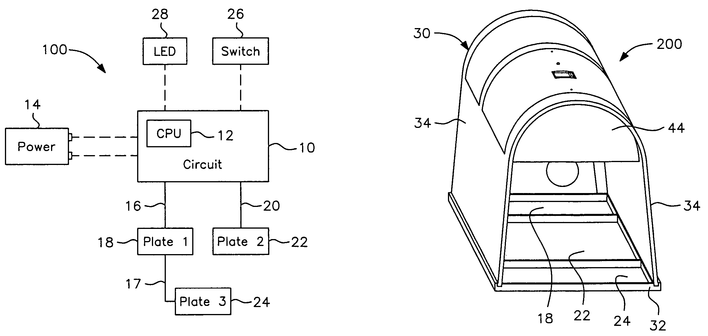
CPU-controlled, rearming electronic animal trap with three-killing-plate configuration

a technology of electronic animal traps and cpu controllers, applied in the field of electric or electronic animal traps, can solve the problems of waste of effort by exterminator personnel or other users, inability to fit larger vermin into traps, etc., and achieve the effects of reducing the likelihood of pest survival, reducing servicing requirements, and reducing the probability of pest survival

Inactive Publication Date: 2007-05-22
WOODSTREAM CORP
View PDF12 Cites 84 Cited by
  • Summary
  • Abstract
  • Description
  • Claims
  • Application Information

AI Technical Summary

Benefits of technology

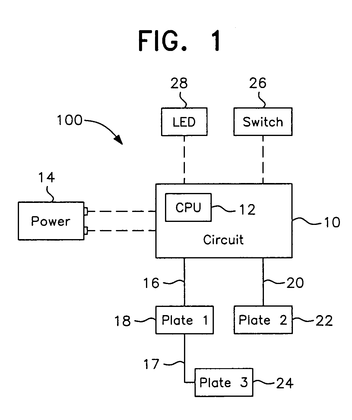
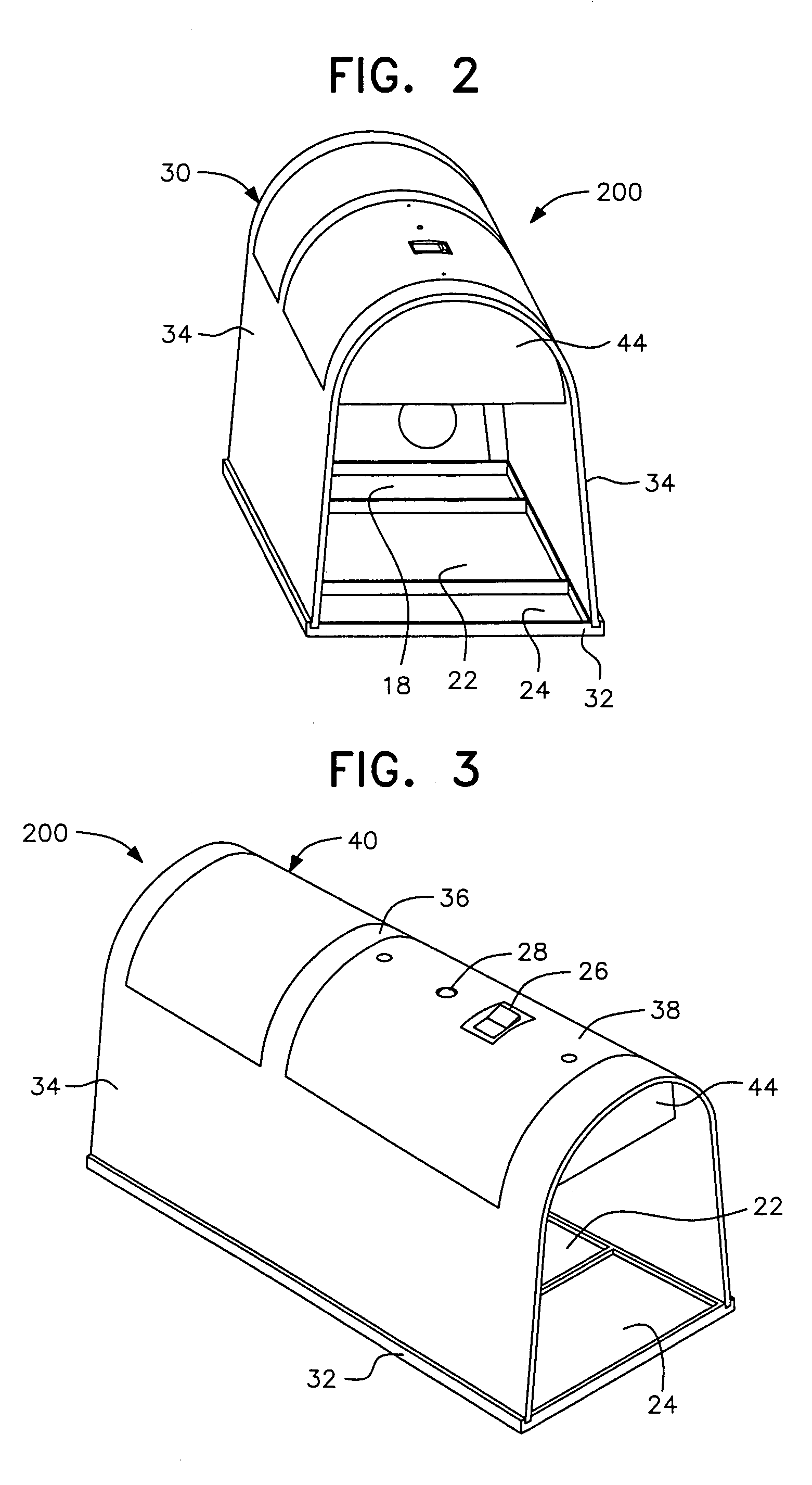
The present invention is an electronically-controlled animal trap that can overcome false-positive indications, have a more powerful electrocution capability, detect the absence of an animal and rearm itself multiple times without requiring human intervention, and reduce the likelihood of pest survival and escape once the trap has been activated. The trap includes a micro-controller chip with a high voltage circuit for generating and delivering a high-voltage pulse train to a set of killing plates for an extended killing cycle. The increased power of the three-killing-plate configuration, combined with the extended killing cycle, provides enhanced kill ratios when dealing with larger, more robust rodents.

Problems solved by technology

While these traps may be used effectively with smaller rodents and insects, a problem still exists with larger pests such as rats in that, while the trap may have been triggered by an animal so as to initiate the kill cycle and subsequent entry into a standby mode requiring service to reset the trap, larger vermin may not have been able to fit into the trap or, if subjected to the voltage, may not have been killed and may have escaped.
As a result, since the standby mode indicates the presence of a dead pest, because it was in fact initiated by a false trigger, wasted effort is expended by exterminator personnel or other users in servicing and resetting a trap which is, in fact, already empty.

Method used


Image

  • CPU-controlled, rearming electronic animal trap with three-killing-plate configuration
  • CPU-controlled, rearming electronic animal trap with three-killing-plate configuration
  • CPU-controlled, rearming electronic animal trap with three-killing-plate configuration

Examples


Embodiment Construction

[0024]Although only a few preferred embodiments of the invention are explained in detail, it is to be understood that other embodiments are possible and likely. Accordingly, it is not intended that the invention is to be limited in its scope to the details of construction and arrangement of components set forth in the following description or illustrated in the drawings. The invention is capable of other embodiments and of being practiced or carried out in various ways. Also, in describing the preferred embodiments, specific terminology will be resorted to for the sake of clarity. It is to be understood that each specific term includes all technical equivalents which operate in a similar manner to accomplish a similar purpose.

[0025]Although the concepts of the instant invention are equally applicable to traps for animals of any size, devices of this type are primarily utilized in connection with the trapping of larger rodents such as rats and, therefore, further discussion herein wi...


PUM


Abstract

An electronic animal trap with a CPU-controlled, rearming, three-killing-plate configuration and extended killing cycle for trapping and exterminating larger rodents such as rats. The high-voltage output circuit is connected to a pair of killing plates which are activated with a high-voltage pulse train for a killing cycle when a pest of known impedance is sensed across said pair of plates. A third killing plate, electrically coupled to a first plate of said pair of plates, is brought to the voltage level of the first plate within approximately 1 msec of circuit activation for increased kill and escape-prevention capabilities.

Description

[0001]This application is entitled to and hereby claims the priority of co-pending U.S. Provisional application, Ser. No. 60 / 499,371 filed Sep. 3, 2003.BACKGROUND OF THE INVENTION[0002]1. Field of the Invention[0003]The invention relates to electric or electronic animal traps, and relates more particularly to an animal trap adapted to catch and electrocute a targeted animal, and also to rearm in the event the continuing presence of the animal is not detected upon completion of a killing cycle.[0004]2. The Prior Art[0005]A number of animal traps have been developed which include structural devices to trap an animal and prevent its escape, along with electric or electronic components which act to kill the trapped animal.[0006]One such device is found in copending application, Ser. No. 10 / 043,161, filed Jan. 14, 2002 (the '161 application), now U.S. Pat. No. 6,609,328, which is hereby incorporated by reference in its entirety. The trap disclosed in the '161 application is virtually esc...

Claims


Application Information

Patent Timeline
Patent Type & Authority Patents(United States)
IPC IPC(8): A01M19/00A01M23/38A01M31/00
CPCA01M23/38A01M31/002
Inventor RICH, CHRISTOPHER T.HARMAN, LARRY L.ANDERSON, DAVID L.
Owner WOODSTREAM CORP
Learn More