
Laser guided work device

a laser guide and work device technology, applied in surveying, navigation, instruments, etc., can solve the problems of unattractive written products, difficult to write in a straight line, and use more writing surface spa

Active Publication Date: 2007-05-22
DALLMAN BRENT
View PDF16 Cites 31 Cited by
  • Summary
  • Abstract
  • Description
  • Claims
  • Application Information

AI Technical Summary

Benefits of technology

Enables precise, straight writing without the need for erasable marks, allowing for customizable line placement and orientation, enhancing the quality and readability of written work.

Problems solved by technology

Unfortunately, when writing free-hand, it is very difficult to write in a straight line.
Quite often the writing moves up and / or down on the writing surface thereby resulting in an unattractive written product, which uses more writing surface space than necessary and / or may be difficult to read.
Unfortunately, this method can leave unsightly eraser marks or leftover pencil marks.
In addition, the eraser may smear the writing.
However, these lines are permanent and their size and location cannot be adjusted according to the writer's needs.
Similar problems arise in engraving, sign-making and other like activities.
For instance, it is difficult for an engraver to engrave in a straight line without the guide of a line.
It is also difficult for a sign-maker or graphic artist to position letters, characters or other objects on a sign, shirt, plaque or other article.

Method used


Image

  • Laser guided work device
  • Laser guided work device
  • Laser guided work device

Examples


Embodiment Construction

[0035]The embodiments hereinafter disclosed are not intended to be exhaustive or limit the invention to the precise forms disclosed in the following description. Rather the embodiments are chosen and described so that others skilled in the art may utilize its teachings.

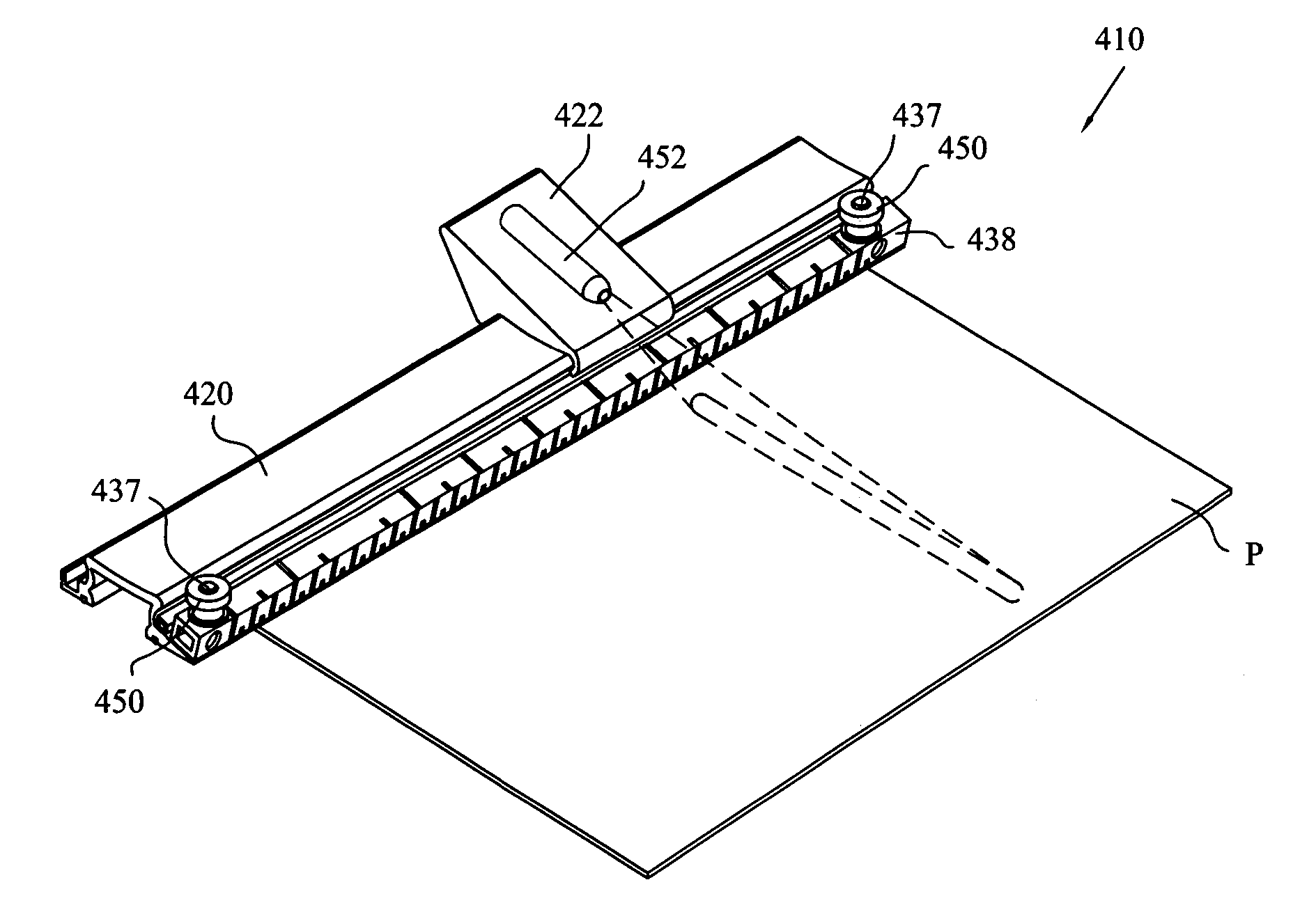
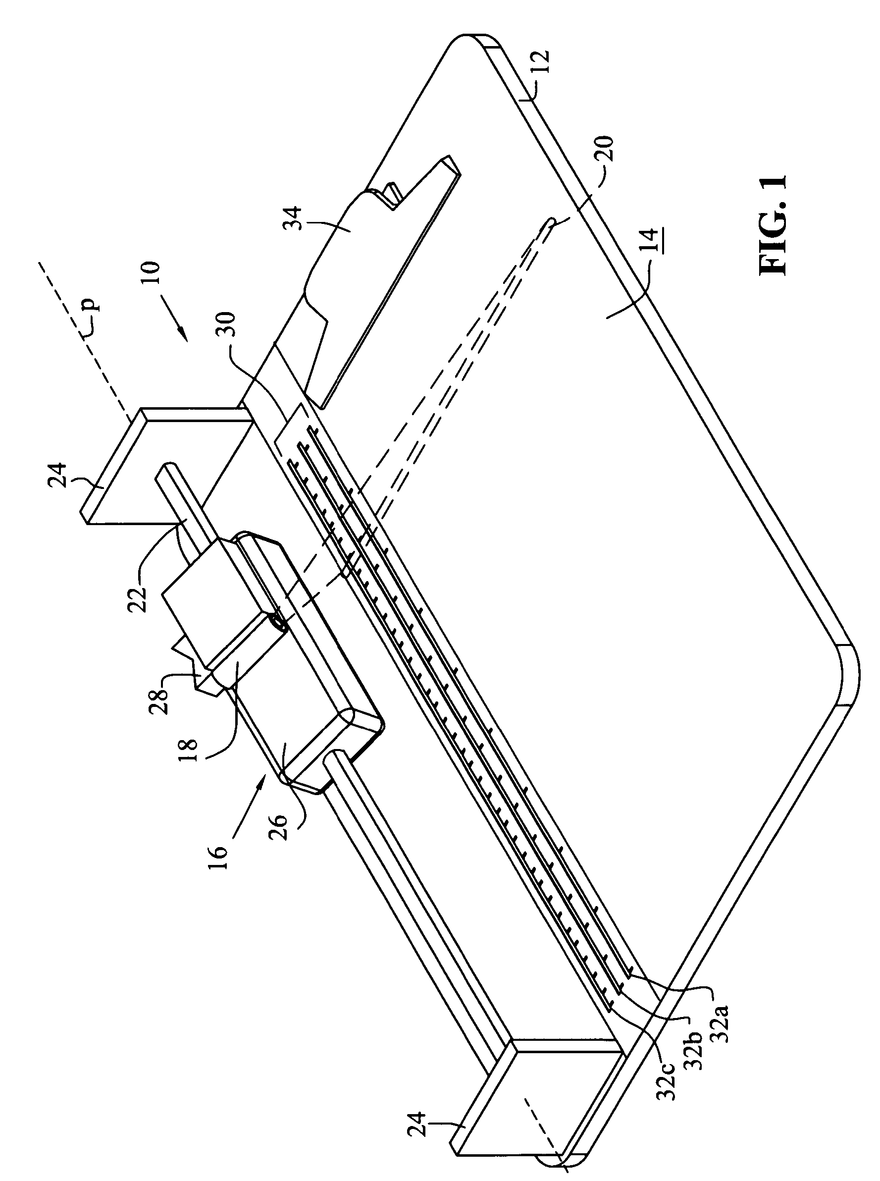
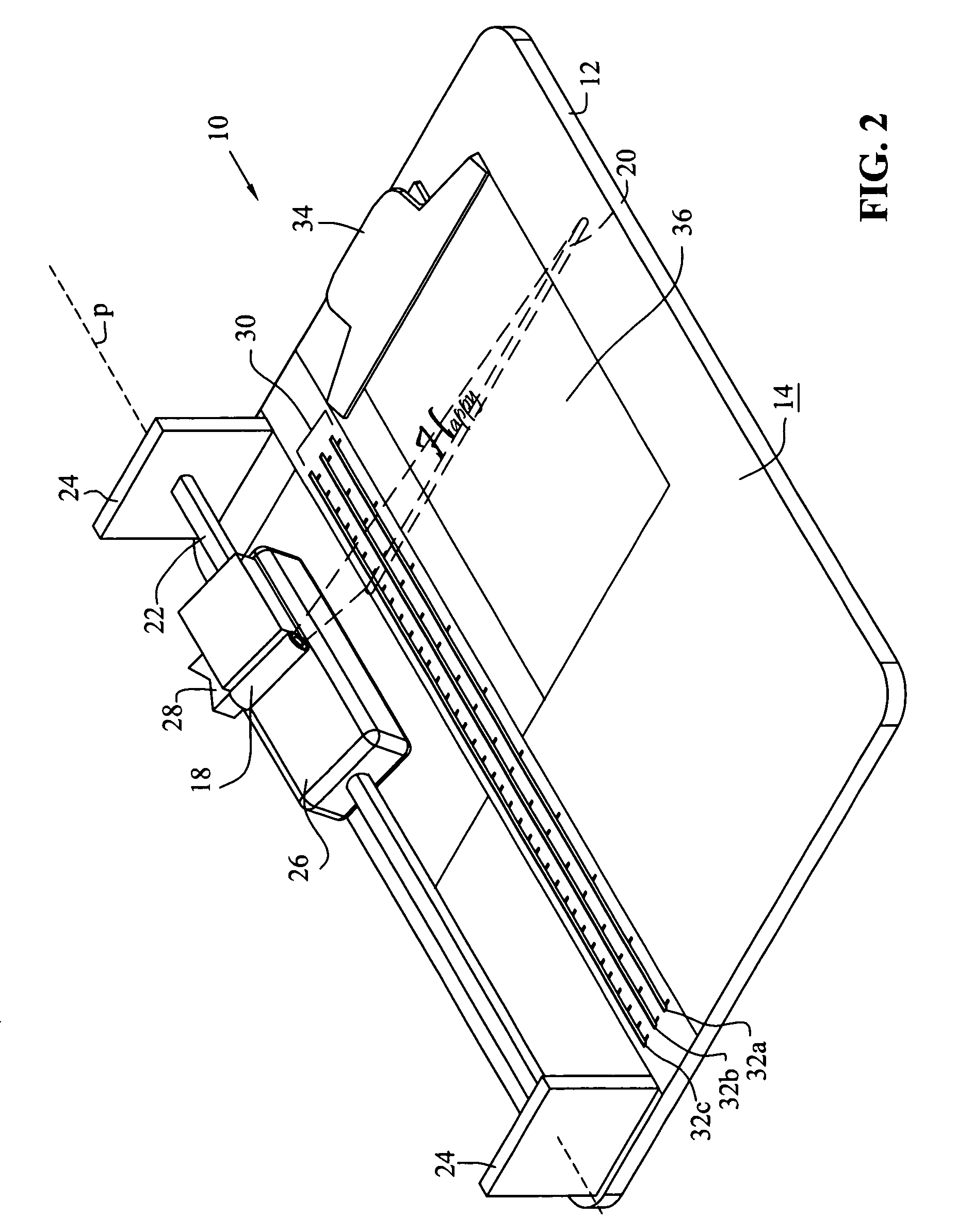
[0036]Referring first to FIGS. 1 and 2, laser guided work device 10 according to one embodiment of the present invention is illustrated. Laser guided work device 10 generally includes work board 12, laser 18 and linear motion device 16. Work board 12 is a hard, rigid structure having work surface 14. Work board 12 may be formed from any rigid material, including for example, metal, vinyl, plastic, PVC (polyvinyl chloride), wood, cardboard, glass, porcelain, or any combination thereof. Furthermore, board may be coated to provide a desired texture. For instance, work board 12 may be formed of metal with a vinyl coating to provide a smooth writing surface.

[0037]Linear motion device 16 is mounted on work board 12 and incl...


PUM


Abstract

A laser guided work device including a work board having a work surface, a line producing laser projecting a line on the work surface, and a linear motion device engaging the laser to the work board. The linear motion device translates the laser relative to the work surface along at least one dimension. The line is oriented perpendicular to the at least one dimension such that the line moves relative to the work surface when the linear motion device translates the laser along the at least one dimension.

Description

PRIORITY REFERENCE[0001]This application is a continuation-in-part application of pending U.S. patent application Ser. No. 11 / 045,410 filed on Jan. 28, 2005 in the name of Brent Dallman and entitled LASER GUIDED WORK DEVICE.BACKGROUND OF THE INVENTION[0002]1. Field of the Invention[0003]The present invention relates to a work device that provides a work surface on which the user can write directly or position a paper for writing thereon.[0004]2. Description of the Related Art[0005]There are several situations in which free-hand writing is necessary or desired. For instance, free-hand writing is typically desired when writing a personal letter on personal stationary, preparing a personalized greeting card, and / or addressing an envelope. In addition, teachers, professors and other instructors must often write in free-hand when writing on a classroom chalkboard or dry erase board. Finally, the art of calligraphy also typically requires the writer to write in free-hand. Unfortunately, w...

Claims


Application Information

Patent Timeline
Patent Type & Authority Patents(United States)
IPC IPC(8): G01C15/00
CPCB42F9/002B42F9/004B43L3/001B43L7/002B43L7/005Y10S33/21
Inventor DALLMAN, BRENT
Owner DALLMAN BRENT
Learn More