
Impulse noise detection from preamble symbols

a preamble and noise detection technology, applied in the field of digital communication, can solve the problems of communication system lockout (or synchronization), interference between a subject symbol and a plurality of symbols, and degraded preamble processing

Inactive Publication Date: 2007-05-08
AVAGO TECH INT SALES PTE LTD
View PDF4 Cites 28 Cited by
  • Summary
  • Abstract
  • Description
  • Claims
  • Application Information

AI Technical Summary

Benefits of technology

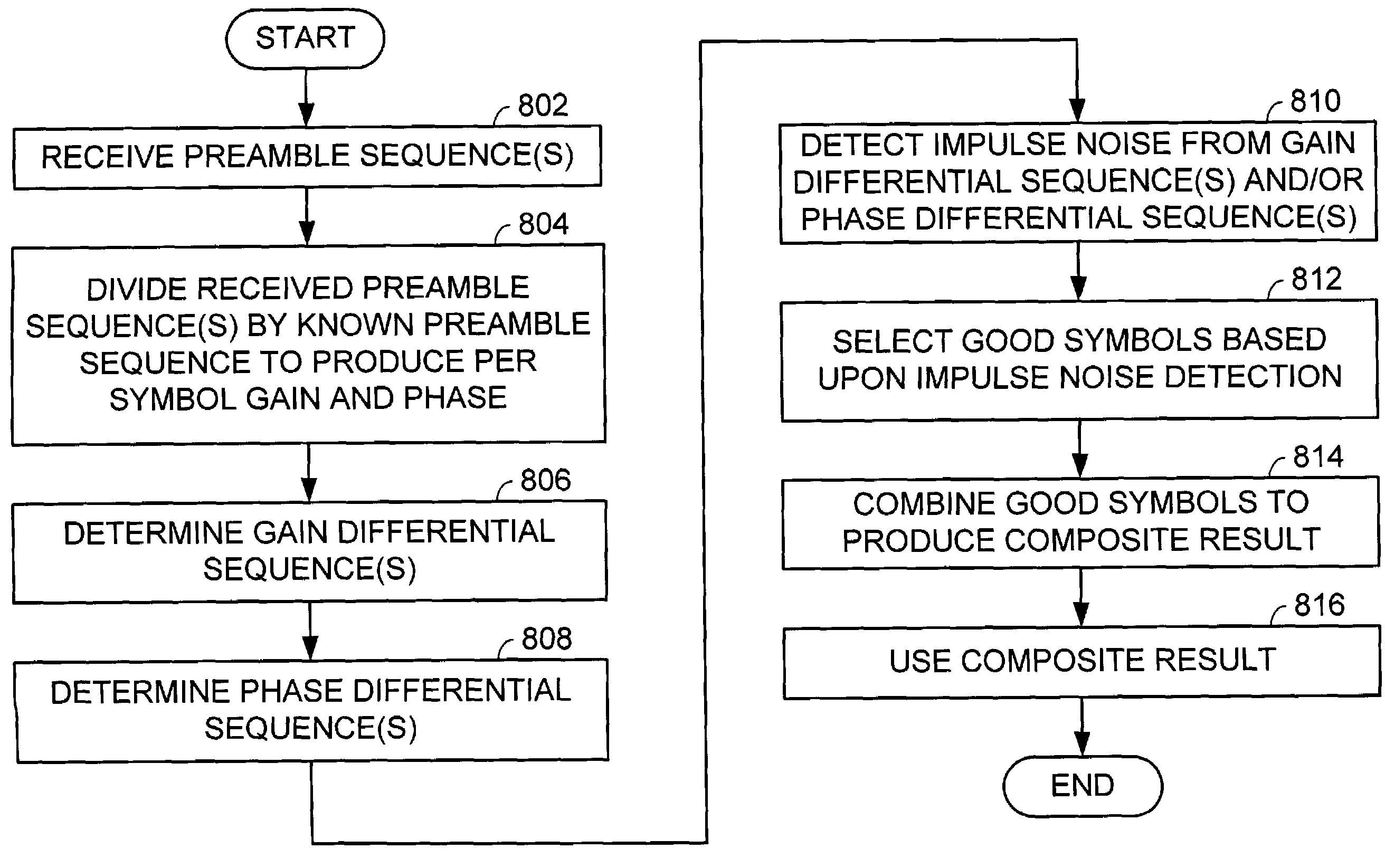
The present invention is a communication device that detects impulse noise in a preamble sequence. The device divides the preamble symbols by a known symbol to produce preamble gains, which are used to determine if any preamble symbol has been affected by impulse noise. The device can discard the affected symbol and apply a correction factor to the non-discarded symbols to produce a composite result. The device can be used for wired or wireless links and can be a cable modem communication system receiver. The technical effect of the invention is to improve the reliability and accuracy of communication signals.

Problems solved by technology

In many communication systems, such as terrestrial based wireless communication systems, satellite based communication systems, cable based communication systems, etc., the channel distorts the transmitted symbols, from the perspective of the receiver, causing interference between a subject symbol and a plurality of symbols surrounding the subject symbol.
Although the burst noise might distort a limited number of preamble symbols, it might be strong enough such that preamble processing is degraded, which causes the communication system to lose lock (or synchronization).
Degradation of preamble processing may lead to system crashes in the case of continuous transmission systems, and packet losses and reduction in the overall system capacity for packet transmission systems.

Method used


Image

  • Impulse noise detection from preamble symbols
  • Impulse noise detection from preamble symbols
  • Impulse noise detection from preamble symbols

Examples


Embodiment Construction

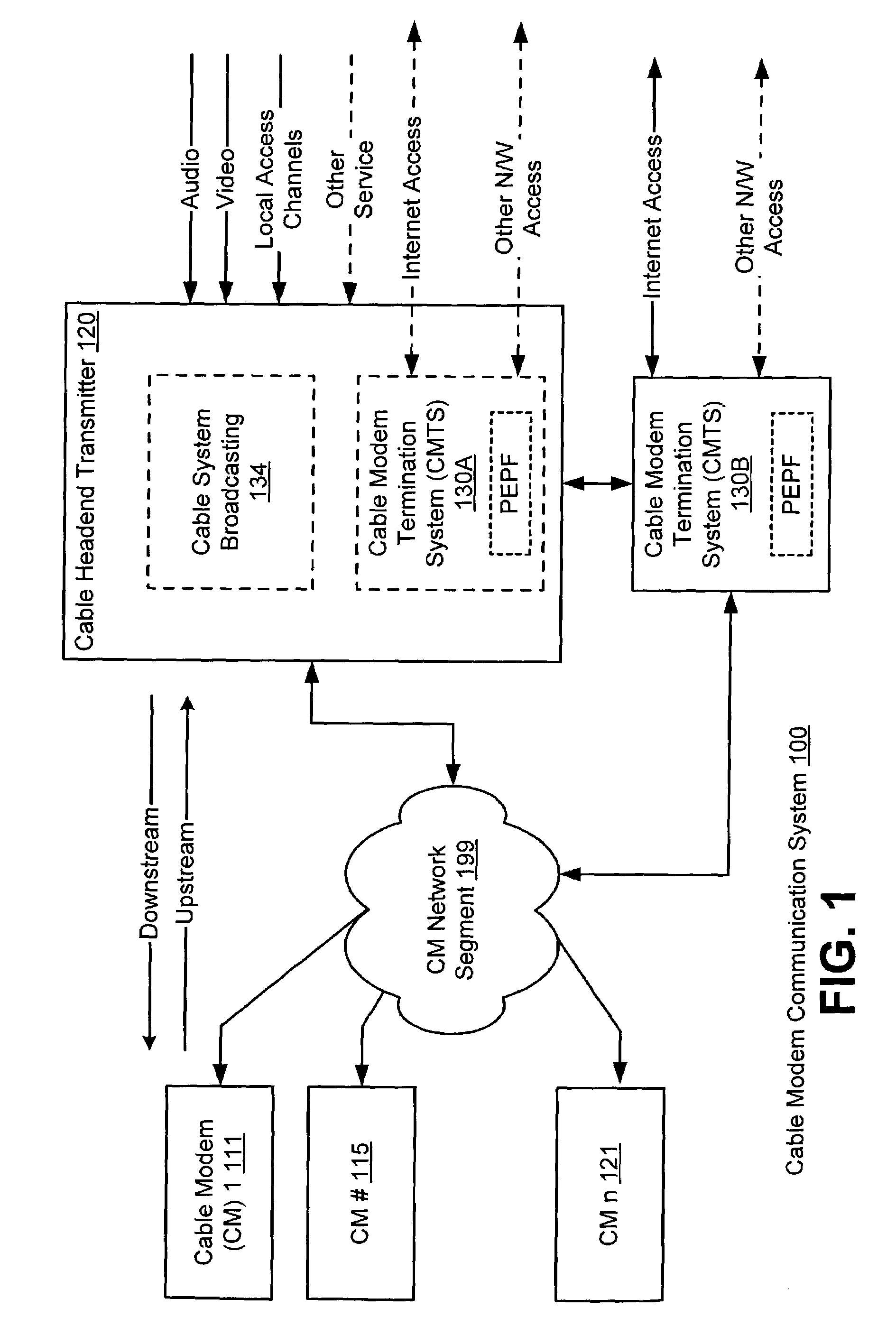
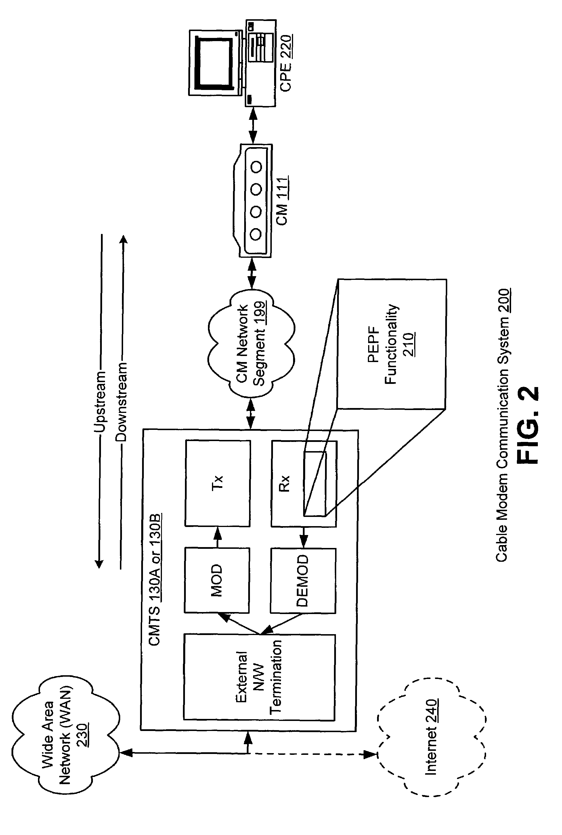
[0032]FIG. 1 is a system diagram illustrating a Cable Modem (CM) communication system 100 that operates according to the invention. The CM communication system 100 includes a number of Cable Modems (CMs), CM 1111, CM 2115, . . . , and CM n 121, a Cable Headend Transmitter 120, and a Cable Modem Termination System (CMTS) 130A or 130B. The CMTS 130A or 130B is a component that exchanges modulated digital information with CMs across a cable network segment 199. A number of elements may be included within the CM network segment 199. For example, routers, splitters, couplers, relays, and amplifiers may be contained within the CM network segment 199 without departing from the scope and spirit of the invention.

[0033]In some embodiments, the CMTS 130A is contained within the Cable Headend Transmitter 120. In other embodiments, a CMTS 130B is located externally with respect to the Cable Headend Transmitter 120. The CMTS 130A or 130B may be located at a local office of a cable television comp...


PUM


Abstract

A communication device constructed according to the present invention detects impulse noise in a preamble sequence. In detecting impulse noise in the preamble sequence the communication device first receive a preamble sequence that includes a plurality of preamble symbols. The communication device then divides the plurality of preamble symbols by at least one known preamble symbol to produce a plurality of preamble gains and / or a plurality of preamble phases corresponding to the plurality of preamble symbols. Finally, the communication device determines, based upon the plurality of preamble gains and / or the plurality of preamble phases, that at least one preamble symbol has been adversely affected by impulse noise. The communication device may discard at least one preamble symbol that has been adversely affected by impulse noise from the plurality of preamble symbols. The communication device may combine non-discarded preamble symbols of the plurality of preamble symbols of the preamble sequence to produce a composite result.

Description

CROSS REFERENCE TO PRIORITY APPLICATION[0001]This application claims priority to U.S. Provisional Application Ser. No. 60 / 416,944, filed Oct. 8, 2002, which is incorporated herein by reference in its entirety for all purposes.BACKGROUND[0002]1. Field of the Invention[0003]This invention relates generally to digital communications; and more particularly to preamble processing in a digital communication system.[0004]2. Background of the Invention[0005]The structure and operation of communication systems is generally known. Many communication systems carry data, e.g., voice, audio, video, file, or other digital data that is sent from a transmitter to a receiver. On the transmitter side, data is first formed into packets. This data may be raw data or encoded data that represents the raw data. Each of these packets also typically includes a header, a known training sequence generally referred to as the “preamble”, and a tail. These packets are then modulated into symbols and the symbols ...

Claims


Application Information

Patent Timeline
Patent Type & Authority Patents(United States)
IPC IPC(8): H03D1/04H04B1/38H04N7/173H04B1/10
CPCH04B1/1027
Inventor YOUSEF, NABIL R.MIN, JONATHAN S.
Owner AVAGO TECH INT SALES PTE LTD
Learn More