Method for sensing the back electromotive force induced in the winding of a voice coil motor

a voice coil motor and electromotive force technology, which is applied in the direction of synchronous motor starters, electronic commutators, information storage, etc., can solve the problems of limiting the maximum switching frequency of the control signal of the switch, the precision of the control speed of the motor, and the damage of the read/write head, so as to reduce the minimum duration toffmin, the effect of shortening the sensing time and increasing the switching frequency of the control signal

Active Publication Date: 2007-05-08
STMICROELECTRONICS SRL
View PDF8 Cites 6 Cited by
  • Summary
  • Abstract
  • Description
  • Claims
  • Application Information

AI Technical Summary

Benefits of technology

[0017]According to the method of the invention for sensing a BEMF, the motor is controlled to force a current pulse, opposite to that circulating in the winding, immediately before tristating the motor. In this way the variation of magnetic flux of the permanent magnet is compensated. As a result, the transient voltage disturbance decays more rapidly, thus allowing for a quicker sensing of the BEMF. Therefore, it is possible to reduce the minimum duration TOFFMIN of the tristate phases, and thus, to increase the switching frequency of the control signals of the driving stage of the motor.

Problems solved by technology

In fact, if the mechanical arm is subjected to strong vibrations, it could flex and the read / write heads could hit the hard disk damaging it or themselves, if not safely parked.
A drawback of this technique is that it is necessary to wait for a minimum time TOFFMIN before the voltage at the terminals approximates with sufficient precision the induced back electromotive force BEMF.
Even when the current transient has decayed, there persists a voltage transient that typically lasts several tenths of microseconds longer, and that may alter the sensing of the BEMF.
These phenomena limit the maximum switching frequency of the control signals of the switches of the driving stage, and as a consequence, the precision of control of the speed of the motor.
This maximum switching frequency typically ranges between 1 kHz and 3 kHz, thus acoustic noise is generated.

Method used


Image

  • Method for sensing the back electromotive force induced in the winding of a voice coil motor
  • Method for sensing the back electromotive force induced in the winding of a voice coil motor
  • Method for sensing the back electromotive force induced in the winding of a voice coil motor

Examples


Embodiment Construction

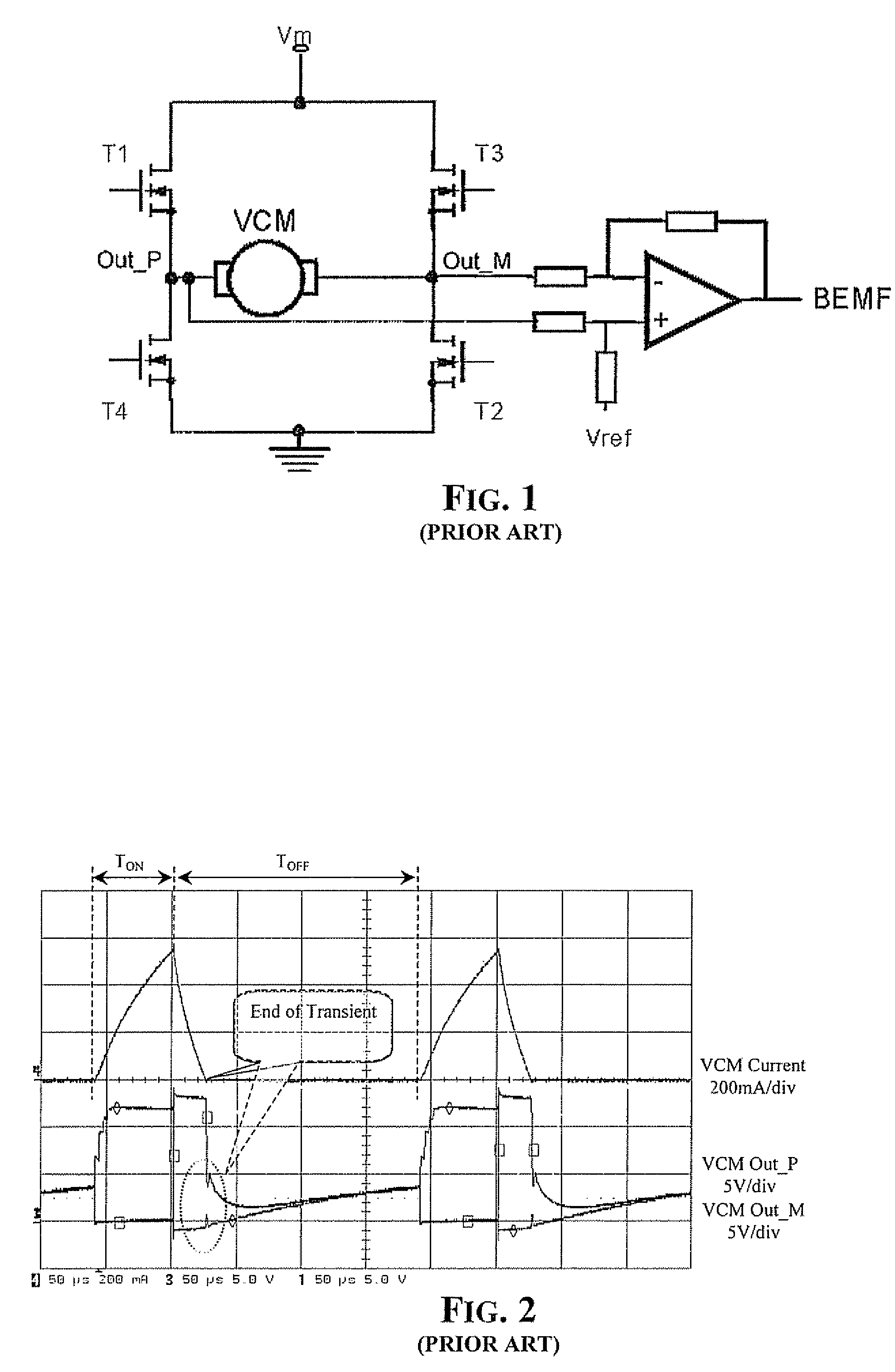
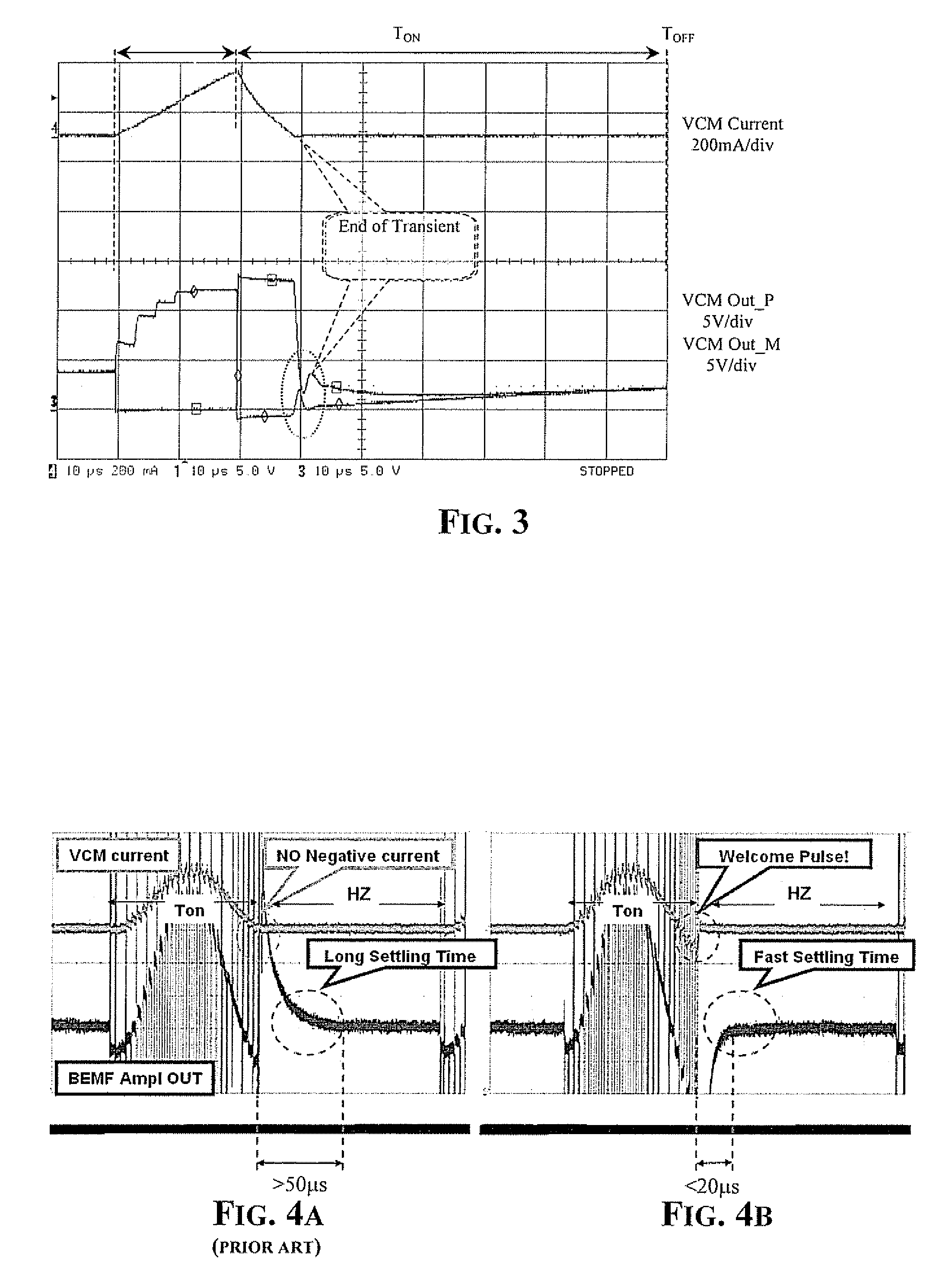
[0022]The method of the invention, similar to the method disclosed in U.S. Pat. No. 6,542,324 and which is incorporated herein by reference in its entirety and is assigned to the current assignee of the present invention, senses the back electromotive force induced in the winding when the motor is tristated. To shorten as much as possible the off-phase and thus be able to increase the switching frequency of the driving stage, the switches of the stage are controlled such that during a final portion of the conduction phase, immediately before entering the successive off-phase, a current opposite to that flowing during an initial fraction of the conduction phase is forced through the winding.

[0023]A current pulse opposing the drive current flowing through the VCM is forced in the winding to invert the direction of flow of the resultant current flowing through the winding during a final portion of the conduction phase. This may be implemented with the same control system of FIG. 1 by c...


PUM

PropertyMeasurementUnit
voltageaaaaaaaaaa
currentaaaaaaaaaa
switching frequencyaaaaaaaaaa

Abstract

A method for sensing a back electromotive force induced in a winding of a voice coil electro-mechanical actuator controlled in a discontinuous mode by alternating conduction phases to off-phases includes sensing voltage at terminals of the winding during an off-phase The winding is driven during a conduction phase immediately preceding the off-phase to invert, during a final portion of the conduction phase before entering an off-phase, a direction of flow of the current through the winding.

Description

FIELD OF THE INVENTION [0001]The invention relates in general to electric motors, and more particularly, to a method for sensing the back electromotive force (BEMF) induced in a winding of a voice coil motor (VCM) or other similar electro-mechanical actuator for improving control of the speed of the motor during load / unload operations of the arm that carries the read / write heads of a hard disk.BACKGROUND OF THE INVENTION [0002]Voice coil motors (VCM) are used in many applications. They are substantially composed of a winding placed in a magnetic field generated by a permanent magnet By forcing a certain current in the windings, a force that displaces the winding is generated. The displacement of the winding may be controlled with high precision.[0003]Besides VCMs, there are other electro-mechanical actuators that work by exploiting this principle, such as audio loudspeakers, electro-locks, etc. Because of the wide use of VCMs, reference will be made to this class of motors, but what...

Claims


Application Information

Patent Timeline
Patent Type & Authority Patents(United States)
IPC IPC(8): G11B21/02
CPCH02P6/182H02P25/028H02P25/034
Inventor MAIOCCHI, GIUSEPPEGALBIATI, EZIOBOSCOLO, MICHELE
Owner STMICROELECTRONICS SRL
Why Eureka
Try Eureka