
Dynamic determination of memory mapped input output range granularity for multi-node computer system

a computer system and multi-node technology, applied in the direction of memory adressing/allocation/relocation, digital computers, instruments, etc., can solve the problems of consuming substantial resources, conventional “base” and “size” type registers fail to provide scalability for memory mapping in a multi-node computer system

Inactive Publication Date: 2007-05-01
FUJITSU LTD
View PDF8 Cites 44 Cited by
  • Summary
  • Abstract
  • Description
  • Claims
  • Application Information

AI Technical Summary

Benefits of technology

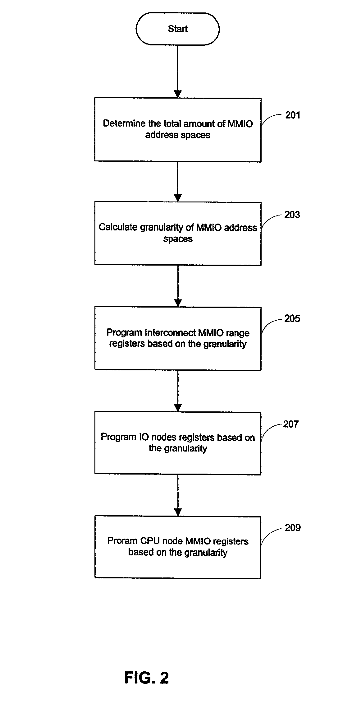
[0008]In accordance with the present invention, there is provided a method and system for dynamically supporting memory mapped IO (MMIO) devices in an interconnect-based multi-node computer system. In particular, the method and system support arbitrarily large amounts of MMIO address space with a fixed number of interconnect range registers and efficiently uses allocated MMIO memory space in a multi-node computer system. In one embodiment, the method includes: (1) dynamically determining a total amount of MMIO address space requirement for all MMIO devices; (2) calculating an optimized value of a MMIO range granularity to support the total MMIO address space requirement; (3) programming MMIO registers of the interconnect based on the determined granularity; and (4) programming IO node controllers and CPU node controllers based on the determined granularity to support all MMIO devices.

Problems solved by technology

Such multi-node computer system may perform complex computing tasks such as interacting simultaneously with a large number of IO devices.
The conventional “base” and “size” type registers thus consume substantial resources.
Moreover, the conventional “base” and “size” type registers fail to provide scalability for memory-mapping in a multi-node computer system.
It would be very inefficient for a programmer to configure every MMIO range register to specify the base and the size in the interconnect for each IO device.

Method used


Image

  • Dynamic determination of memory mapped input output range granularity for multi-node computer system
  • Dynamic determination of memory mapped input output range granularity for multi-node computer system
  • Dynamic determination of memory mapped input output range granularity for multi-node computer system

Examples


Embodiment Construction

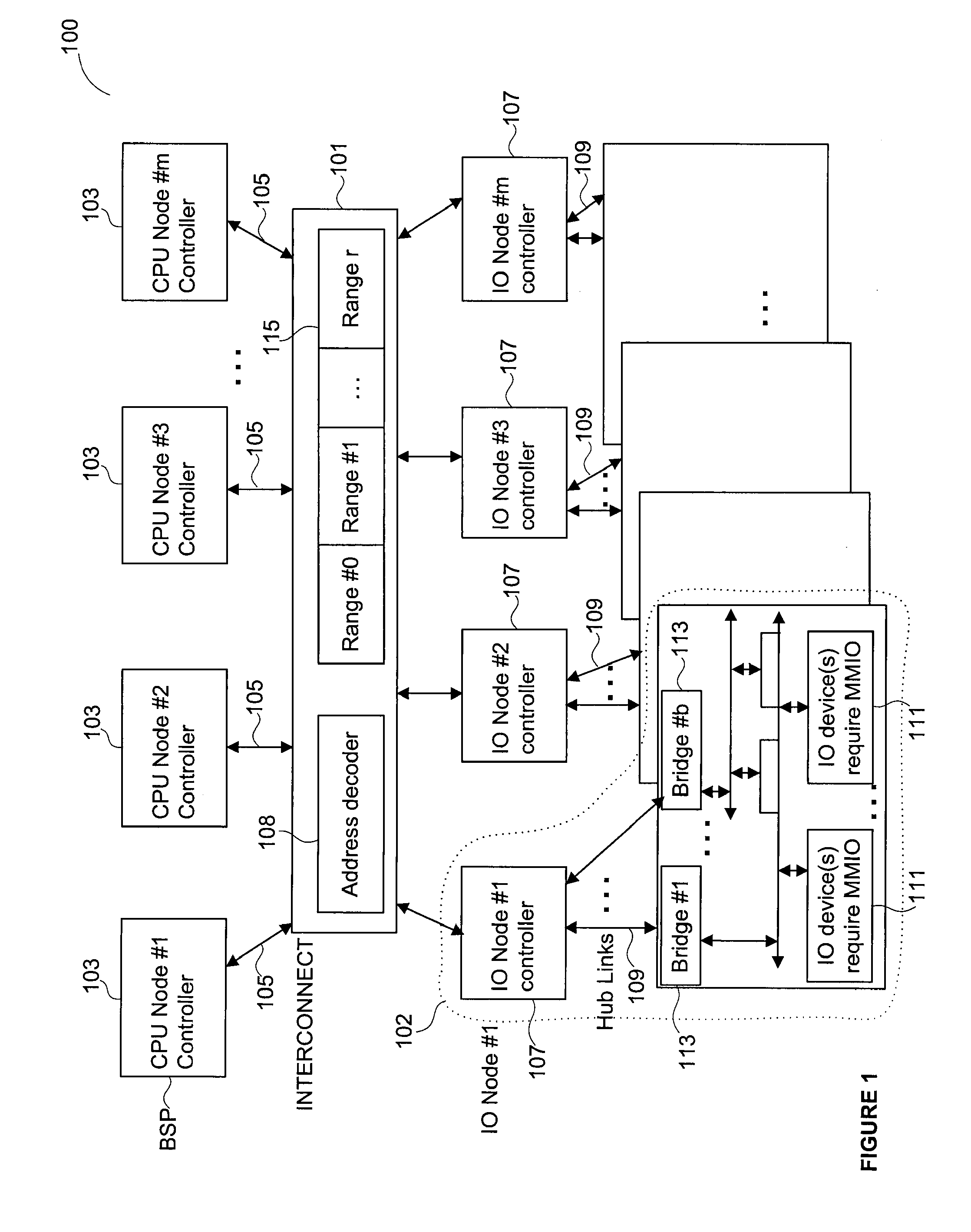
[0013]FIG. 1 illustrates a multi-node computer system 100 that typically contains a plurality of central processing units (CPU) node controllers 103 (#1, #2, #3, . . . #n), an interconnect 101, and a plurality of Input / Output (IO) nodes 102. The CPU nodes controllers 103 and the IO nodes 102 are all coupled to the interconnect 101. Typically, each of the CPU node controllers 103 is coupled to the interconnect 101 through a scalability port 105. A multi-node computer system 100 may also include multiple interconnects 101. Each of the interconnects 101 routes commands and data among different nodes and devices in the system 100. The details of an interconnect-based multi-node computer system are well known in the art, and are not included here to avoid obscuring a clear description of the present invention.

[0014]Within each IO node 102, there is typically included an IO node controller 107, and bridges 113 and IO devices 111. Different groups of IO devices 111 are respectively coupled...


PUM


Abstract

A method and system enables dynamic support of memory mapping devices in a multi-node computer system. One of central process unit (CPU) nodes determines a total amount of MMIO address spaces that are needed for all MMIO devices and generates an optimized granularity to support the total amount of MMIO address spaces. Based on the granularity, a CPU node controller configures MMIO range registers of the interconnect and other MMIO registers in IO nodes and CPU node controllers to support dynamic changes of MMIO address space requirements of the system.

Description

RELATED APPLICATION[0001]This application claims priority under 35 U.S.C. § 119(e) from co-pending U.S. Provisional Patent Application Ser. No. 60 / 301,955, entitled “Algorithm For Dynamically Determining The Memory Mapped Input Output Range Granularity For A Multi-Node Computer System,” filed on Jun. 29, 2001, by Prabhunandan B. Narasimhamurthy, et al, which is incorporated by reference in its entirety herein.FIELD OF THE INVENTION[0002]The present invention relates generally to an interconnect-based multi-node computer system, in particular, to supporting memory mapped Input Output (MMIO) processing for a multi-node computer system.BACKGROUND OF THE INVENTION[0003]A multi-node computer system typically contains a plurality of central processing units (CPU) node, a plurality of interconnects, and a plurality of input output (IO) nodes. Each IO node is coupled to multiple IO devices, which may be conventional peripheral devices, such as peripheral component interconnect (PCI), small ...

Claims


Application Information

Patent Timeline
IPC IPC(8): G06F3/00G06F13/14G06F12/06G06F15/177
CPCG06F12/063
Inventor NARASIMHAMURTHY, PRABHUNANDAN B.NISHIMURA, YUKIOMIRYALA, SUDHEERMASUYAMA, KAZUNORI
Owner FUJITSU LTD
Learn More