
Method of agile reduction of radar cross section using electromagnetic channelization

a radar cross section and electromagnetic channelization technology, applied in the direction of instruments, communication jamming, and antennas, can solve the problems of limiting the design possibilities of aircraft, failing to use existing stealth technologies, and not turning into useful technologies, etc., and achieve the effect of reducing the radar cross section

Inactive Publication Date: 2007-05-01
ALAN ROSS
View PDF27 Cites 28 Cited by
  • Summary
  • Abstract
  • Description
  • Claims
  • Application Information

AI Technical Summary

Benefits of technology

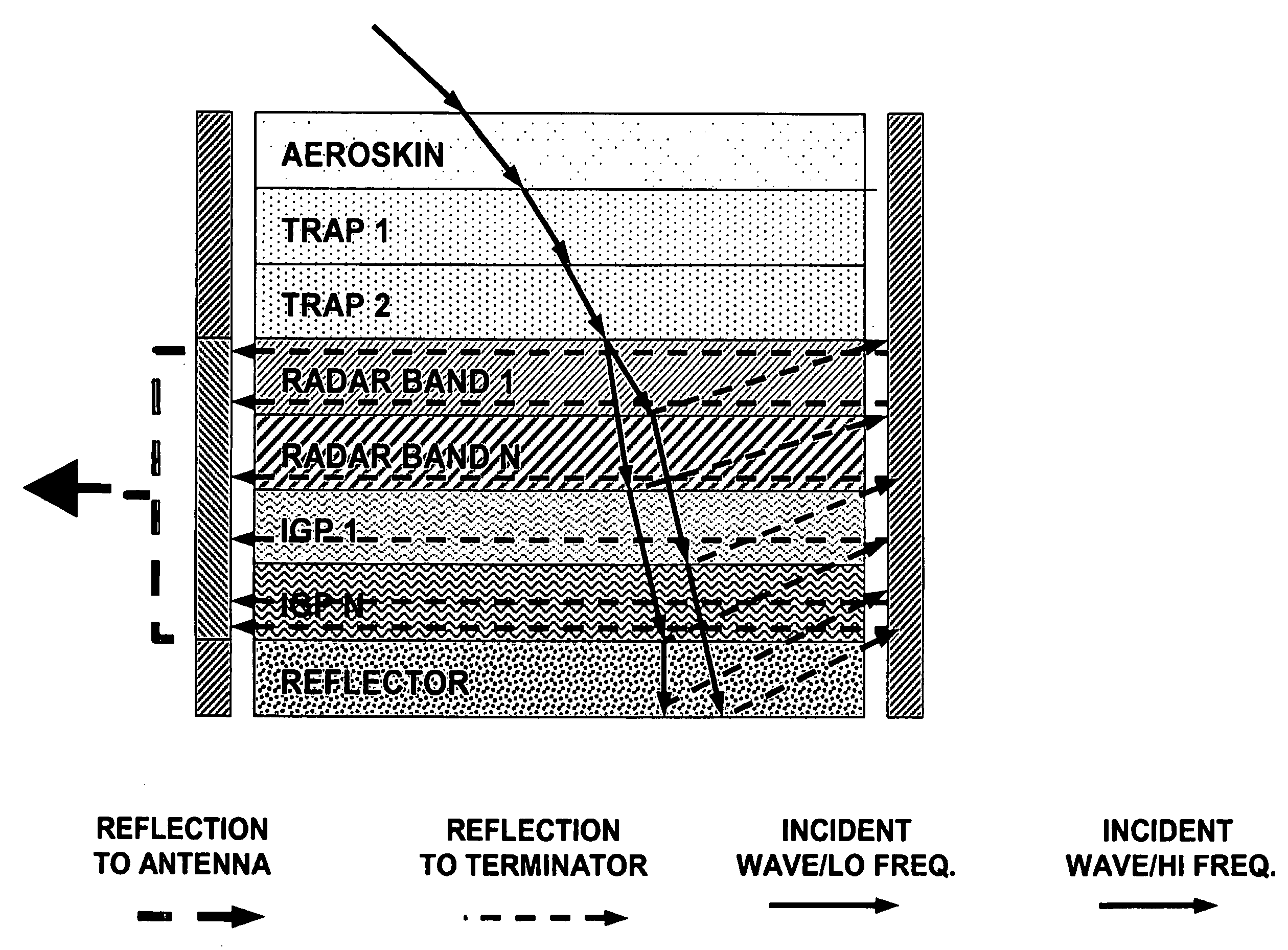
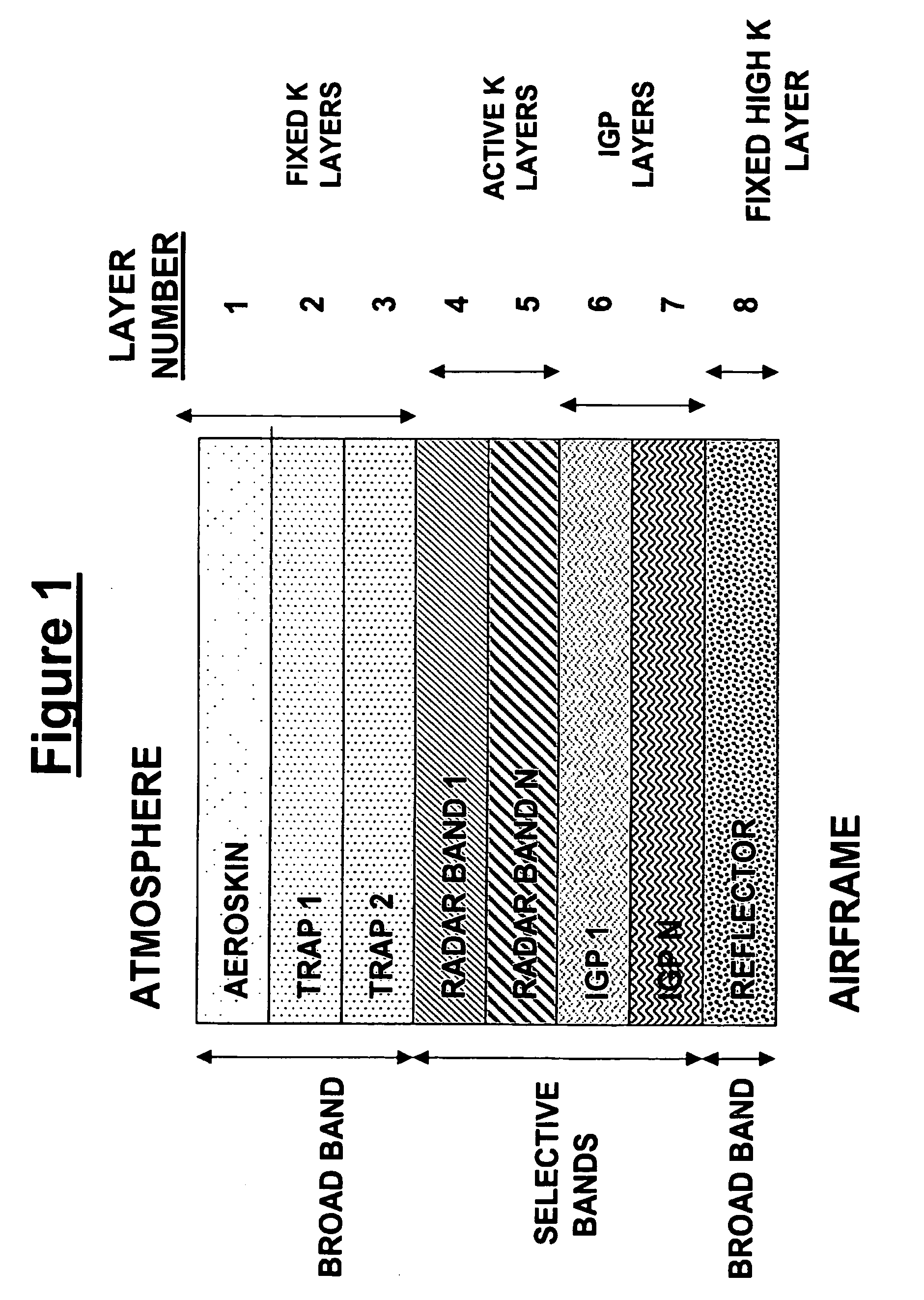
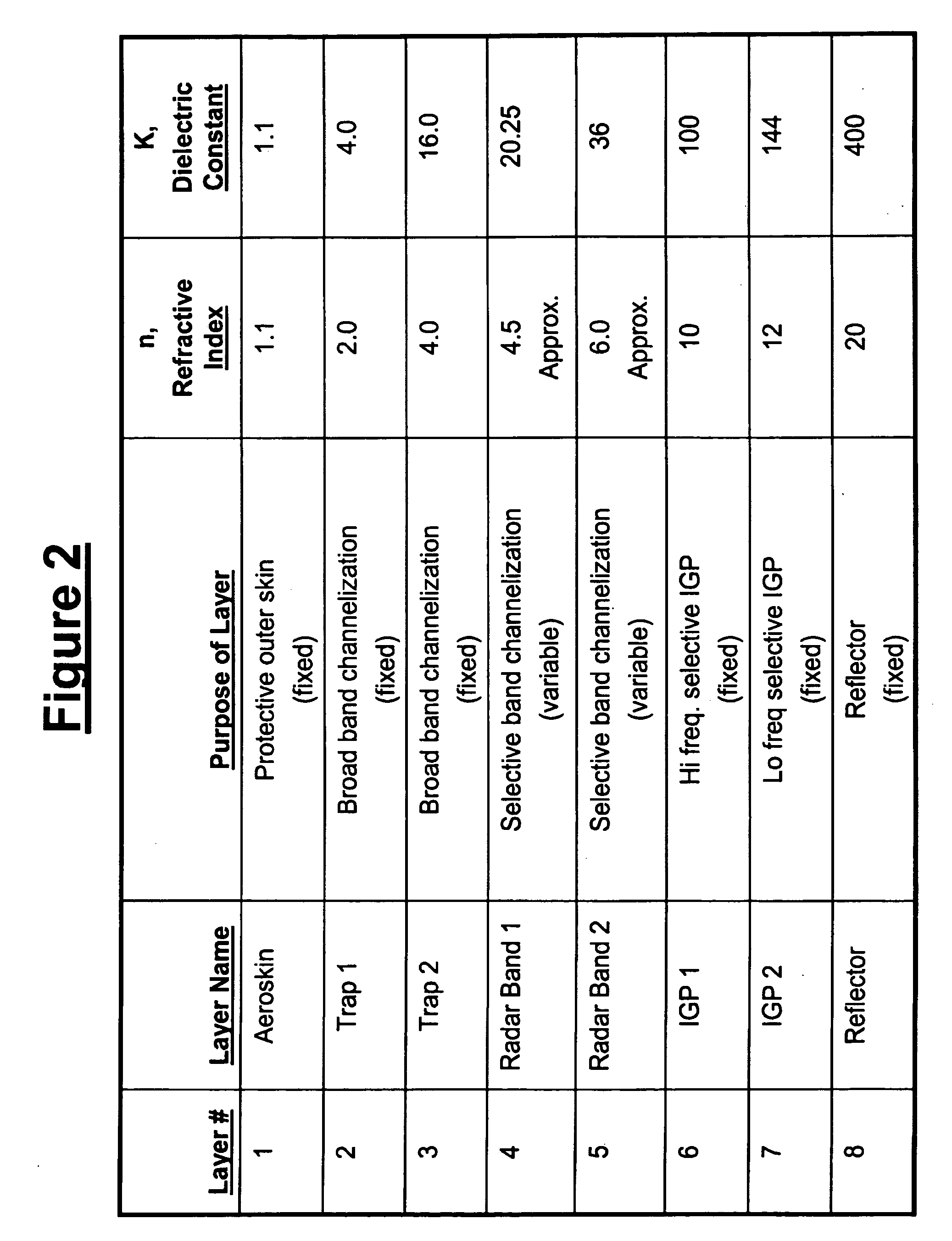
"The invention is about a way to make objects invisible to radar. It does this by using a special structure that traps or dissipates radar waves, making the object invisible to radar scanning. This structure can be applied to objects that already have stealth capabilities or can be added to objects that previously had no stealth capability. The layers in the structure include fixed and variable dielectric layers, as well as interference generating patterns that deflect certain wavelengths of electromagnetic radiation. The structure can also include a reflector for reflecting certain wavelengths of electromagnetic radiation. The invention can be used on vehicles, such as aircraft, and can make them invisible to radar scanning."

Problems solved by technology

Radar, an acronym for “Radio Detection and Ranging”, systems was originally developed many years ago but did not turn into a useful technology until World War II.
This is an undesirable outcome of the RAM approach.
The problem with this approach is that the triangles can only protect against a particular radar frequency, so that multiple triangles are required or the aircraft can be detected by different frequencies.
Such a geometric design limits the design possibilities for the aircraft.
In addition, there are short failings with existing Stealth technologies such as the use of toxic chemicals in the construction, susceptibility to the effects of weather and abrasive materials such as sand, as well as continued high levels of maintenance.
But most importantly, there are two major flaws with current Stealth technology.
First of all, the techniques outlined above are a permanent fixture of the airframe and cannot be altered or removed without adversely affecting the either the Stealthy or the aerodynamic characteristics of the Stealth aircraft.
As such, non-Stealthy aircraft and other vehicles can not be made to take on Stealthy characteristics once they are constructed, commissioned and deployed.
Secondly, Stealth technologies currently in use cannot alter, adjust, adapt or modulate the RCS of a particular Stealthy design in response to new, different or varying radar frequencies employed by an adversary.

Method used


Image

  • Method of agile reduction of radar cross section using electromagnetic channelization
  • Method of agile reduction of radar cross section using electromagnetic channelization
  • Method of agile reduction of radar cross section using electromagnetic channelization

Examples


Embodiment Construction

[0043]This invention, known as Method of Agile Reduction of Radar Cross Section Using Electromagnetic Channelization (MARRCS), relates to technology for providing an active method of reducing Radar Cross Section (RCS) of aircraft or other vehicle being scanned by threat detection radars. This technology will be both portable and scalable to accommodate a variety of aircraft, or other vehicles, not equipped with existing “Stealth” technology. It may also to provide dynamic and agile stealth capabilities to aircraft currently deployed with only the existing static Stealth technology. It is intended to use nanotechnology, where appropriate, reduce weight, provide support and insure airframe conformity. This technology will not adversely affect the aerodynamic characteristics of the aircraft.

[0044]Furthermore, the technology will be active in that it will provide optimum protection from radars operating at different or varying frequencies. The net result will be an agile radar “sponge” ...


PUM


Abstract

A method for reducing radar cross section of an object that has conductive portions and that is expected to be scanned by radar, which includes providing the object with a multiple layer radar cross section reducing structure that reduces or entraps or dissipates radar waves therein so that the size or configuration of the object cannot be correctly detected by radar scanning. The invention also relates to the radar cross section reducing structure alone or associated with an object such as a vehicle that transports personnel or equipment. The structure can be provided on an object that previously has no stealth capability or it can be applied to an object that already has stealth capability for increasing its capability to prevent correct detection by radar scanning.

Description

TECHNICAL FIELD[0001]This invention relates to technology for providing an active method of reducing Radar Cross Section (RCS) of aircraft and other vehicles being scanned by threat detection radars.BACKGROUND OF THE INVENTION[0002]Radar, an acronym for “Radio Detection and Ranging”, systems was originally developed many years ago but did not turn into a useful technology until World War II.[0003]One component of a basic radar system is typically a transmitter subsystem which sends out pulse of high frequency electromagnetic energy for a short duration. The frequencies are typically in the Gigahertz (GHz) range of billions of cycles per second. When such a pulse encounters a vehicle made of conducting material (such as metal), a portion of the energy from the incoming pulse is reflected back. If this reflected energy is of a sufficient magnitude, it may be detected by the receiver subsystem of the radar. The computer subsystem which controls the radar system knows when the pulse was...

Claims


Application Information

Patent Timeline
Patent Type & Authority Patents(United States)
IPC IPC(8): H01Q17/00G01S13/00
CPCH01Q17/00
Inventor MESSANO, AL
Owner ALAN ROSS
Learn More