
Artificial fireplace

a technology of artificial fireplaces and flames, applied in the field of artificial fireplaces, can solve the problems of unrealistic flame image, high price of traditional fireplaces, and inability to produce realistic flame images, and achieve the effect of less undesirable heat inside the fireplace and realistic flame imag

Inactive Publication Date: 2007-05-01
ELITEGROUP COMPUTER SYSTEMS
View PDF21 Cites 37 Cited by
  • Summary
  • Abstract
  • Description
  • Claims
  • Application Information

AI Technical Summary

Problems solved by technology

However, traditional fireplaces are expensive, create smoke, and are a fire hazard so artificial fireplaces or stoves are popular alternatives.
Heretofore, the biggest problem with artificial fireplaces is that they do not produce a realistic flame image.
While this creates the image of a flickering flame, the image is not realistic because the result is an orange glow.
The usual light source in an artificial fireplace is a monochromatic light bulb, which results in an unrealistic orange glow.
Some prior art fireplaces attempt to create a multi-colored flame by using rotating flame elements of different colors, but this does not produce a realistic flame image.
This results in an unsatisfactory flame effect and disadvantageously shortens the lifespan of the light source by repeatedly cycling it on and off.
In addition, there are other problems associated with using one or more light bulbs as a light source.
First, light bulbs have a relatively short life span and they must be replaced frequently.
Furthermore, light bulbs produce a fair amount of heat and, depending on the material used to form the components disposed within the fireplace, this can create a fire hazard.
Finally, light bulbs consume more electricity than do other light-producing devices.

Method used


Image

  • Artificial fireplace
  • Artificial fireplace
  • Artificial fireplace

Examples


Embodiment Construction

[0023]As required, detailed embodiments of the present invention are disclosed herein; however, it is to be understood that the disclosed embodiments are merely exemplary of the invention, which may be embodied in various forms. Therefore, specific details disclosed herein are not to be interpreted as limiting, but merely as a basis for the claims and as a representative basis for teaching one skilled in the art to variously employ the present invention in virtually any appropriate manner.

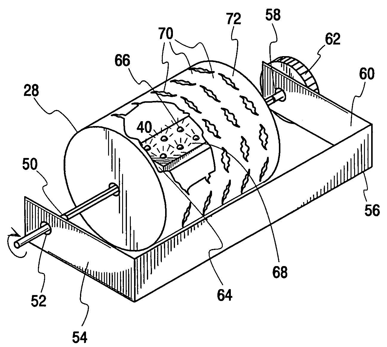
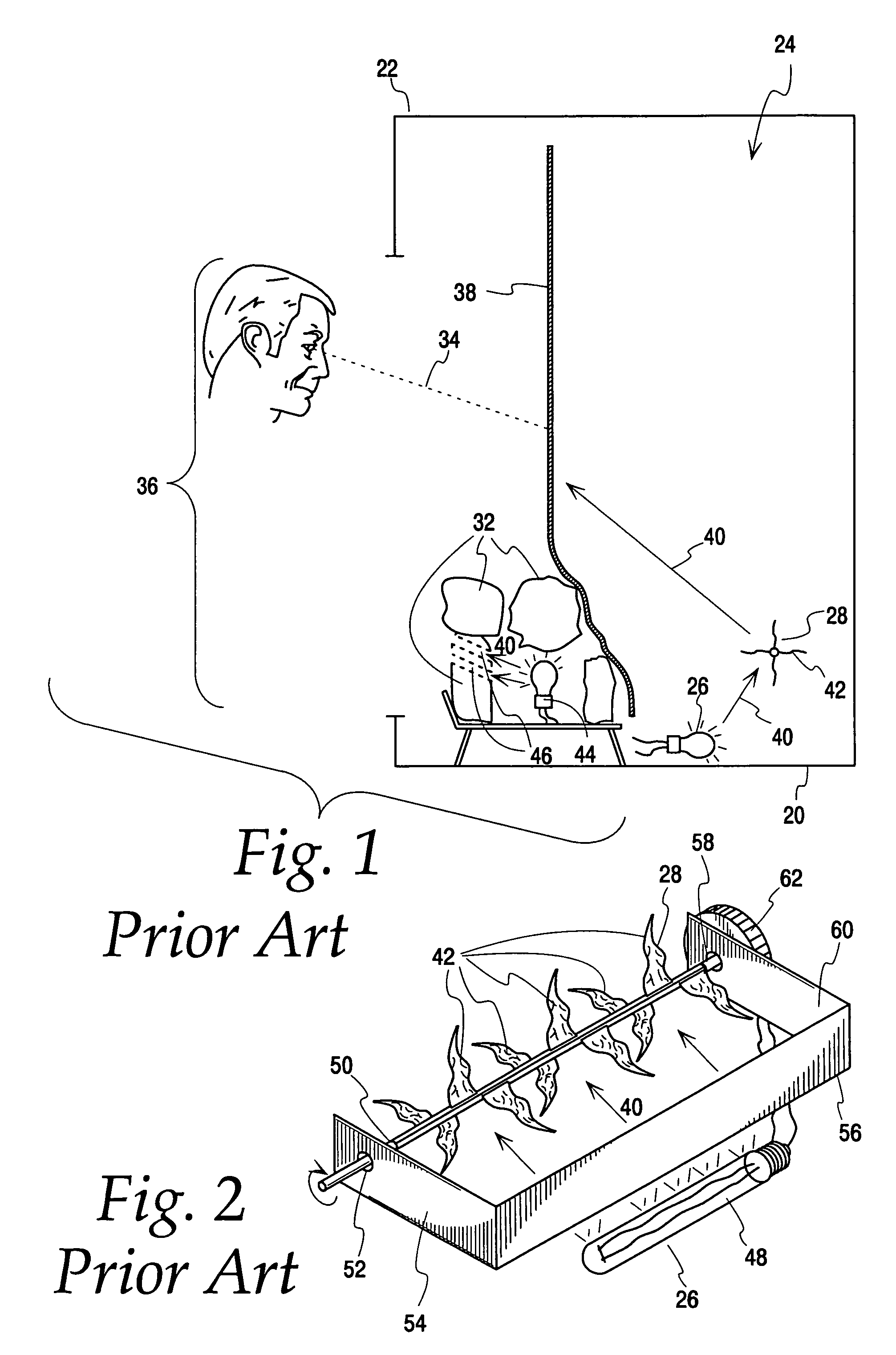
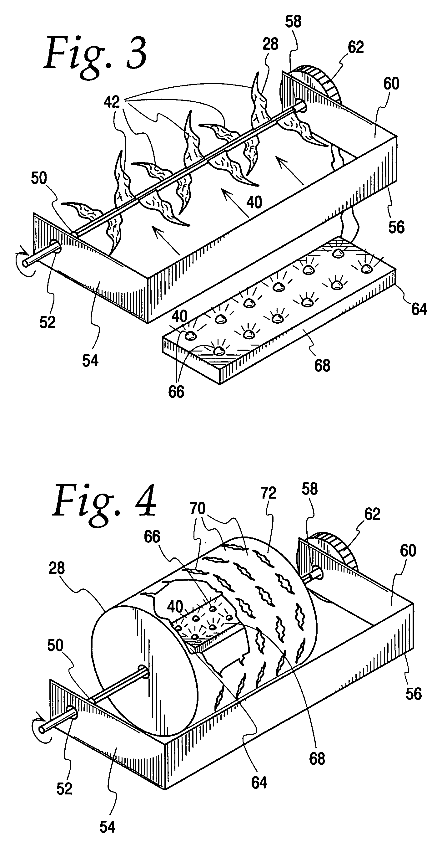
[0024]FIG. 3 illustrates a preferred embodiment that is generally similar in operation to the structure shown in FIGS. 1 and 2. One important difference between the structure shown in FIG. 3 and the one shown in FIGS. 1 and 2 is the addition of an improved light source 64. The light bulb 48 of the prior art light source 26 is replaced by a plurality of light emitting diodes (LEDs) 66 which are removably affixed to a printed circuit board (PCB) 68. The LEDs 66 and PCB 68 are operatively coupled to a...


PUM


Abstract

An artificial fireplace for simulating flaming logs has a housing containing a solid state light source, a rotating flame simulation assembly, a viewing screen, and a simulated fuel source. The solid state light source preferably comprises light emitting diodes (LEDs) affixed to a printed circuit board. The light produced by the LEDs reflects off of the rotating flame simulation assembly and an image of a flame is transmitted onto the viewing screen. This design creates a realistic, randomly-flickering flame image above the simulated fuel source. Optional features include a dimmer assembly to adjust the intensity of the image and a second light source to simulate smoldering embers within the simulated fuel source. This design eliminates the problems associated with using a light bulb for a light source by instead using LEDs with a longer life span which emit less undesirable heat and consume less electricity.

Description

CROSS REFERENCE TO RELATED APPLICATION[0001]This is a continuation-in-part application of application Ser. No. 10 / 982,287, filed Nov. 5, 2004.FIELD OF THE INVENTION[0002]This invention generally relates to artificial fireplaces.BACKGROUND OF THE INVENTION[0003]Fireplaces are common household devices that are used to provide heat and a pleasing aesthetic. However, traditional fireplaces are expensive, create smoke, and are a fire hazard so artificial fireplaces or stoves are popular alternatives. Artificial fireplaces are less expensive than traditional fireplaces and they do not use actual flames, so there is no smoke or fire hazard.[0004]Typically, an artificial fireplace is formed from a ceramic housing with a viewing aperture and a hollow interior. The ceramic housing contains a light source, a viewing screen, a flame simulation device, and a simulated fuel source. The light source is disposed on the bottom of the interior of the housing, underneath the flame simulation device an...

Claims


Application Information

Patent Timeline
Patent Type & Authority Patents(United States)
IPC IPC(8): G09F19/00
CPCF24C7/004Y10S362/806
Inventor ROSSEROT, JEAN PIERRE
Owner ELITEGROUP COMPUTER SYSTEMS
Learn More