Control method for jerk-limited speed control of a movable machine element of a numerically controlled industrial processing machine

a technology of numerical control and control method, which is applied in the direction of electric programme control, ignition automatic control, program control, etc., can solve the problems of slow acceleration buildup, shorter program processing time, and higher path speed, so as to achieve significant improvement of the dynamic properties of the machine, without sacrificing accuracy

Inactive Publication Date: 2007-04-24
SIEMENS AG
View PDF10 Cites 10 Cited by
  • Summary
  • Abstract
  • Description
  • Claims
  • Application Information

AI Technical Summary

Benefits of technology

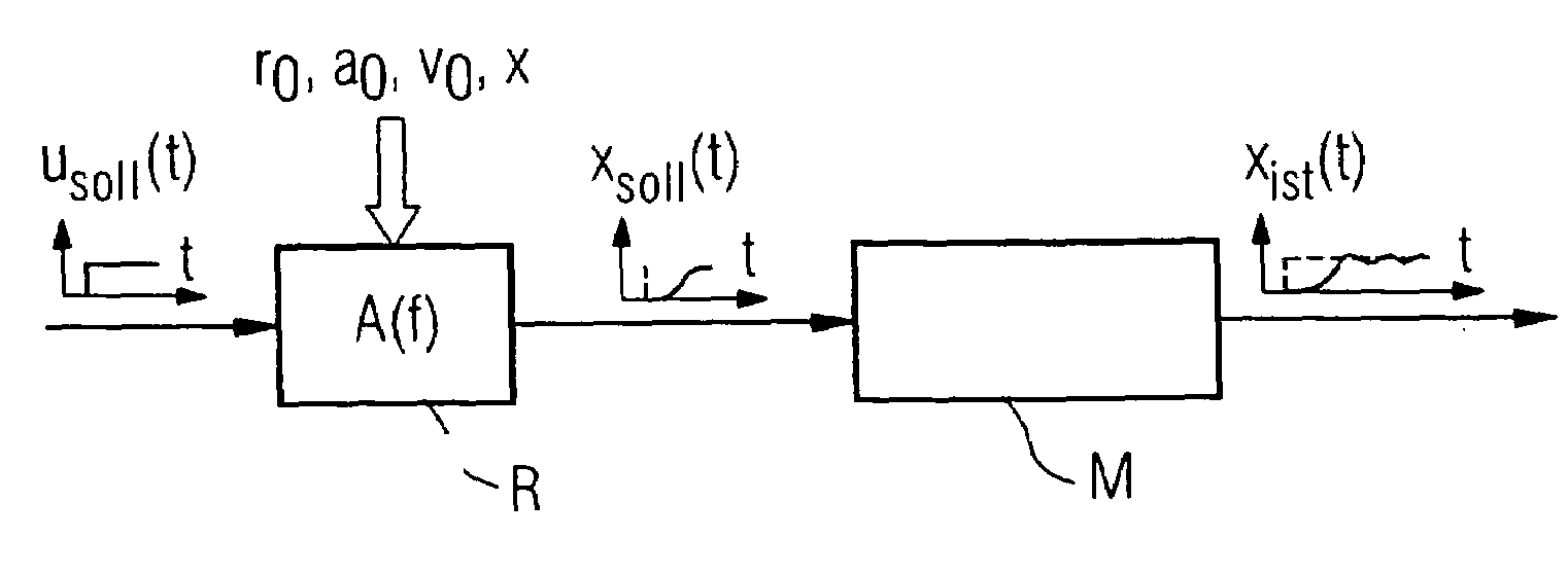
[0015]The control method according to the present invention describes a new approach whereby, unlike with the conventional method, not a specific shape function is selected, but an optimal shape function is computed based on the dominant characteristic frequencies of the machine. In this way, the dynamic properties of the machine can be significantly improved over the conventionally attained dynamic properties of the machine without sacrificing accuracy.

Problems solved by technology

A jerk limitation can slow down the buildup of the acceleration of a machine movement so as to smooth the desired value and to move the machine mechanism with the smallest possible oscillation excitation.
However, setting the dynamic values very low often prevents a higher path speed and hence also a shorter program processing time, which would be otherwise desirable.
The aforementioned problem is that acceleration and braking processes with a high dynamic range along the travel path x of the machine element can still cause mechanical oscillations in a certain frequency range.

Method used


Image

  • Control method for jerk-limited speed control of a movable machine element of a numerically controlled industrial processing machine
  • Control method for jerk-limited speed control of a movable machine element of a numerically controlled industrial processing machine
  • Control method for jerk-limited speed control of a movable machine element of a numerically controlled industrial processing machine

Examples


Embodiment Construction

[0036]Throughout all the Figures, same or corresponding elements are generally indicated by same reference numerals. These depicted embodiments are to be understood as illustrative of the invention and not as limiting in any way. It should also be understood that the drawings are not necessarily to scale and that the embodiments are sometimes illustrated by graphic symbols, phantom lines, diagrammatic representations and fragmentary views. In certain instances, details which are not necessary for an understanding of the present invention or which render other details difficult to perceive may have been omitted.

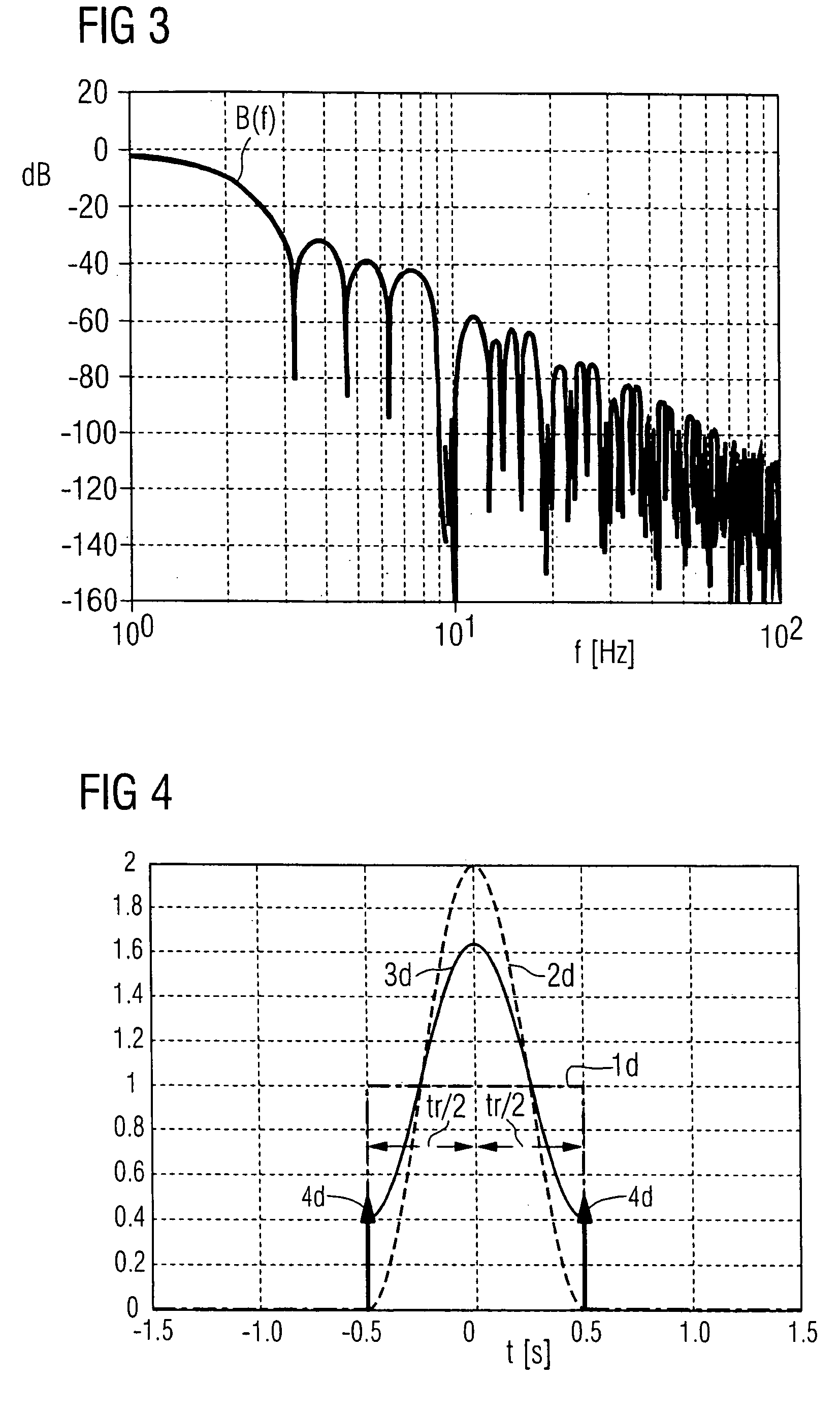
[0037]Turning now to the drawing, and in particular to FIG. 1, there is shown an exemplary rectangular jerk profile r(t) as a function of time t. The term “jerk” herein refers to the time derivative of the acceleration a(t). The jerk profile r(t) is characterized by its maximum jerk height r0 as well as by the various times tr, ta and tv that describe the motion path of the mo...


PUM


Abstract

A control method for controlling a speed of a movable machine element of a numerically controlled industrial processing machine with jerk limitation is described. The processing machine can be, for example, a machine tool, a production machine and / or a robot. A travel path of the movable machine element is first decomposed into a plurality of sequentially arranged, interpolatable travel sections. Jerk profiles are then determined for the interpolatable travel sections, which are modified with a parameter-dependent shape function. The modified jerk profiles provide a filter action that can be represented by bandpass filters having blocking frequencies. The blocking frequencies of the bandpass filters are selected so as to substantially correspond to characteristic frequencies of the machine element. The control method significantly improves the machine dynamics without sacrificing accuracy.

Description

CROSS-REFERENCES TO RELATED APPLICATIONS[0001]This application claims the priority of German Patent Application, Serial No. 103 15 525.2, filed Apr. 4, 2003, pursuant to 35 U.S.C. 119(a)–(d), the disclosure of which is incorporated herein by reference.BACKGROUND OF THE INVENTION[0002]The present invention relates to a control method for jerk-limited speed control of a movable machine element of a numerically controlled industrial processing machine, such as a machine tool, production machine or a robot. In the context of this application, the term “production machine” is used in a generic sense and also includes robots which generally follow the concepts outlined here.[0003]A mechanical system that is capable of performing oscillations (e.g., along the axes of the machine tool) is typically characterized by at least one characteristic frequency which is excited by a movement or displacement and which can be observed in the actual position value. Excitations of the various mechanisms...

Claims


Application Information

Patent Timeline
IPC IPC(8): G05B19/416G05B7/02G05B19/18G05B19/41
CPCG05B19/416G05B2219/41232G05B2219/43065G05B2219/43178
Inventor LADRA, UWESCHAFERS, ELMAR
Owner SIEMENS AG
Why Eureka
Try Eureka