System and method for operating a fuel injector

A technology of fuel injection system and fuel injector, which is applied to fuel injection device, fuel injection control, charging system, etc., to achieve the effect of reducing emission and improving control

Pending Publication Date: 2019-07-09
FORD GLOBAL TECH LLC
View PDF0 Cites 0 Cited by
  • Summary
  • Abstract
  • Description
  • Claims
  • Application Information

AI Technical Summary

Problems solved by technology

Therefore, for long main fuel injections, the fuel injector may inject a different amount of fuel than expected

Method used


Image

  • System and method for operating a fuel injector
  • System and method for operating a fuel injector
  • System and method for operating a fuel injector

Examples


Embodiment Construction

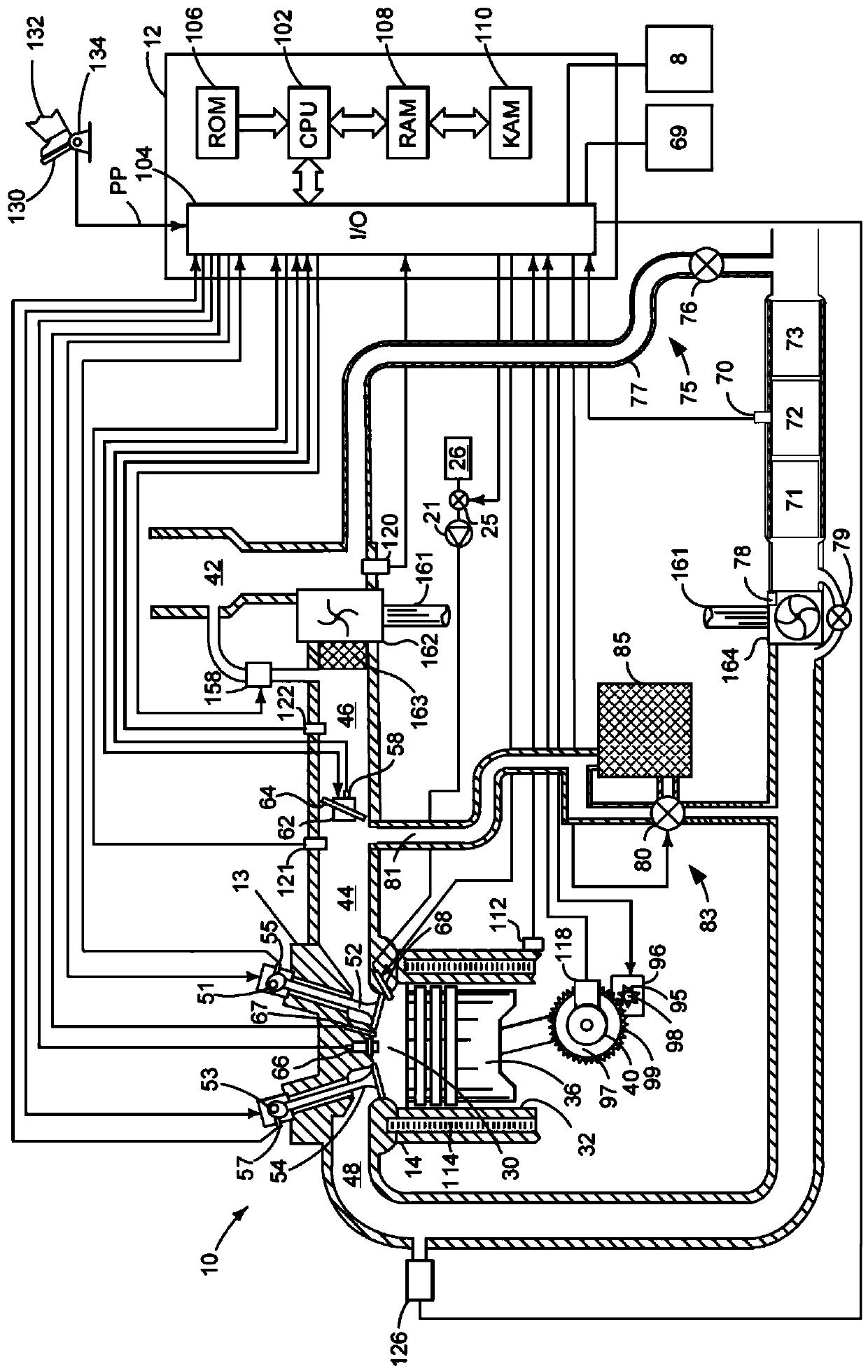
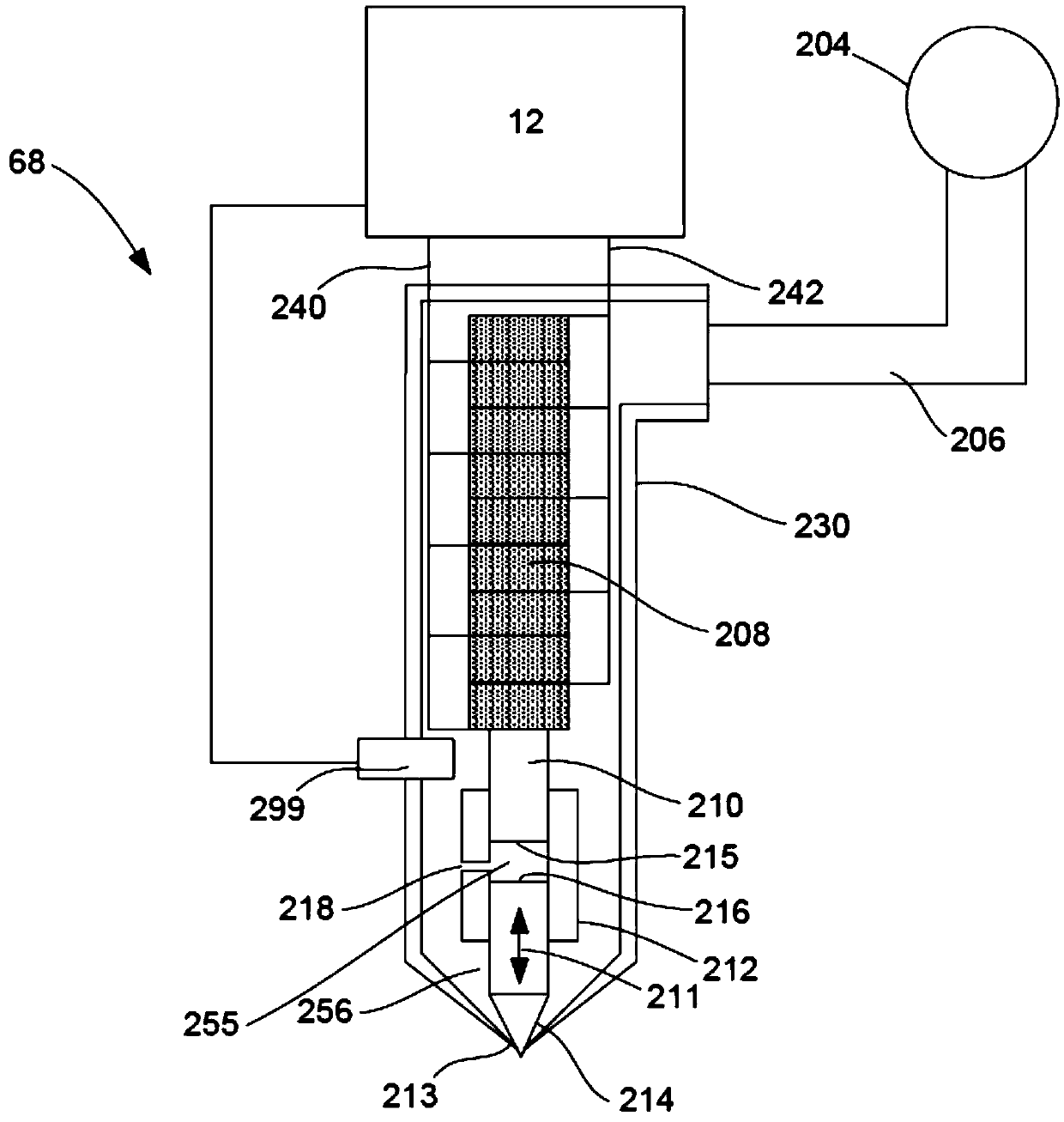
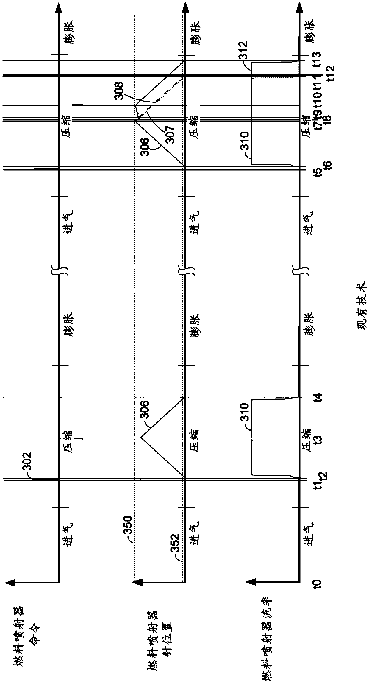
[0015] Operations covered in this manual include figure 1 Diesel engine with direct fuel injectors shown. The fuel injector may be figure 2 type shown. image 3 A prior art fuel injector operating sequence is shown in . Figure 4 The fuel injector operating sequence according to this specification is shown in . Figure 5 A method for operating a direct fuel injector and engine is shown in . Image 6 A graph showing injected fuel quantity versus fuel injector energization time is shown in .

[0016] refer to figure 1 , an internal combustion engine 10 (which includes a plurality of cylinders, one of which is figure 1 shown in ) is controlled by the electronic engine controller 12. Controller 12 from figure 1 The various sensors receive signals and adopt figure 1 The various actuators are used to adjust engine operation based on the signals received and instructions stored on the controller's memory.

[0017] Engine 10 includes combustion chamber 30 and cylinder walls...


PUM


Abstract

The disclosure provides a system and a method for operating a fuel injector. Methods and systems for operating a direct fuel injector of an internal combustion engine are described. In one example, anozzle needle is moved in two directions to maintain fuel flow through the direct fuel injector and to reduce the possibility of the nozzle needle impacting a piezoelectric actuator. The method and system may permit long fuel injection times without causing undesirable impacts between components of a fuel injector.

Description

technical field [0001] The present invention relates to the field of vehicle fuel injectors. Background technique [0002] Diesel fuel injectors may inject fuel into cylinders of the engine multiple times during a cycle of the cylinders. Fuel injection may include pilot fuel injection, main fuel injection, and post fuel injection. There may be several pilot fuel injections during a cylinder cycle, and the duration of these pilot fuel injections may be short. Pilot fuel injection can help reduce combustion noise and engine HC and CO emissions. The main fuel injection may be followed by the pilot fuel injection. The duration of the main fuel injection can be much longer than the pilot fuel injection because the fuel in the main fuel injection can provide a large amount of energy that the engine can use to generate torque. The duration of the post fuel injection may also be relatively short compared to the main fuel injection. Post fuel injection may be used to improve the...

Claims


Application Information

Patent Timeline
Patent Type & Authority Applications(China)
IPC IPC(8): F02D41/40
CPCF02D41/402F02D2041/389F02D41/2096F02D41/403F02D41/405F02M51/0603F02M61/10Y02T10/40F02D28/00
Inventor 凯尔·波尔坎普埃里克·库尔茨
Owner FORD GLOBAL TECH LLC
Why Eureka
Try Eureka