subsampling motion detector

A technology of sampling action and detector, applied in the direction of instruments, measuring devices, automatic power control, etc., can solve the problems of increased power consumption and achieve the effect of reduced power consumption

Active Publication Date: 2020-07-31
RICHWAVE TECH CORP
View PDF9 Cites 0 Cited by
  • Summary
  • Abstract
  • Description
  • Claims
  • Application Information

AI Technical Summary

Problems solved by technology

In this case, although the high-frequency oscillating signal will not be divided by the frequency divider, the phase detector must perform phase detection with a fast detection rate, which will lead to an increase in power consumption

Method used


Image

  • subsampling motion detector
  • subsampling motion detector
  • subsampling motion detector

Examples


Embodiment Construction

[0052] Hereinafter, the present invention will be described in detail with several embodiments and with reference to the drawings, so that those skilled in the art can easily understand and implement the present invention. The inventive concepts of the present invention can be implemented in various forms, but the embodiments mentioned therein are not intended to limit the present invention. For the sake of clarity, descriptions of well-known parts will be omitted, and similar symbols represent similar components throughout the description.

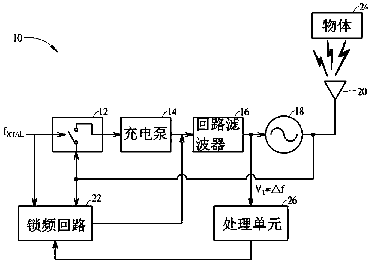
[0053] Please refer to figure 1 . figure 1A motion detector 10 according to the first embodiment of the present invention is shown. The motion detector 10 is mainly composed of analog components, and includes a transceiver 20, a subsampling phase detector (SSPD) 12, a charge pump (charge pump) 14, a loop filter 16, and a voltage-controlled oscillator. (Voltage-Controlled Oscillator; VCO) 18 and Frequency Lock Loop (FLL) 22 . Wherein, ...


PUM


Abstract

The invention discloses a sub-sampling motion detector, which is used for detecting motion information of a measured object, receiving a first radio frequency signal and transmitting a second radio frequency signal. The first radio frequency signal is generated by the reflection of the object by the second radio frequency signal. The sub-sampling motion detector includes a controllable oscillator for outputting an oscillating signal, wherein the first radio frequency signal is injected into the controllable oscillator to control the controllable oscillator through injection locking. The sub-sampling motion detector also has a sub-sampling phase detector, which generates a control signal according to the oscillation signal generated by the controllable oscillator and the reference frequency. The sub-sampling phase detector outputs a control signal to the controllable oscillator to control the controllable oscillator. The oscillation signal of the controllable oscillator is locked to a multiple of the reference frequency, and the control signal includes the motion information of the object.

Description

technical field [0001] The present invention relates to a motion detector, in particular to a subsampling motion detector for detecting motion of a detected object. Background technique [0002] Generally, motion detectors use the Doppler Effect to detect the displacement state of an object, and the Doppler Effect requires a high-frequency signal output from a high-frequency oscillation source to update The displacement state of the object. Many of these motion detectors use a Phase Lock Loop (PLL) to stabilize the high frequency oscillating signal. However, PLLs are generally implemented in one of two ways. In the first way, a frequency divider is used to divide the frequency of the high-frequency oscillating signal before the frequency-divided signal is compared with the low-frequency reference signal by the phase detector. Unfortunately, the frequency divider consumes a lot of power when the PLL is in operation. In another alternative, a high frequency reference signa...

Claims


Application Information

Patent Timeline
Patent Type & Authority Patents(China)
IPC IPC(8): H03L7/099H03L7/093
CPCH03L7/093H03L7/099G01S13/56H03L7/091H03L7/087H03L7/24H03L7/06
Inventor 陈则朋
Owner RICHWAVE TECH CORP
Why Eureka
Try Eureka