
Inducer, and inducer-equipped pump

a technology of inducer and inducer, which is applied in the direction of liquid fuel engines, marine propulsion, vessel construction, etc., can solve the problems of reducing the suction capability of the pump, affecting the reliability of the pump, and the inability to improve the blade shape of the inducer, so as to suppress the reverse flow at the inlet. , the effect of high reliability

Inactive Publication Date: 2007-04-24
EBARA CORP
View PDF7 Cites 18 Cited by
  • Summary
  • Abstract
  • Description
  • Claims
  • Application Information

AI Technical Summary

Benefits of technology

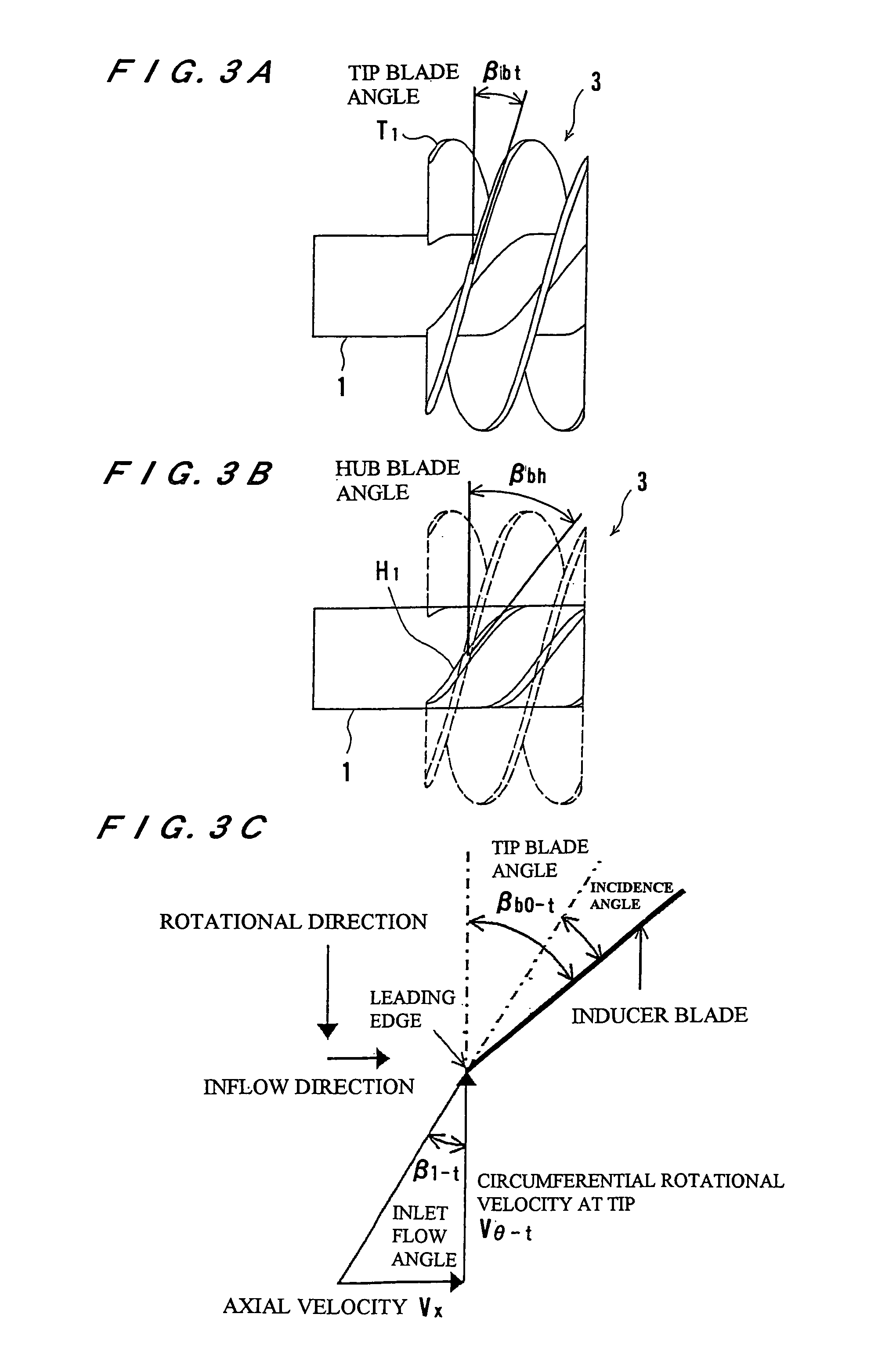
"The present invention provides an inducer and a pump with an inducer that are highly reliable and can suppress a reverse flow at the inlet while satisfying a required head and suction capability. The inducer has a blade angle at the blade leading edge that is substantially the same as the inlet flow angle at a designed flow rate, which reduces the incidence angle of the flow and effectively suppresses a reverse flow at the inlet. The blade angle distribution on the tip and hub from the blade leading edge to the blade trailing edge is designed to distribute the load on the blade along the tip and maintain a sufficient suction capability. The pump with an inducer has a main impeller mounted on a rotatable shaft, and the inducer is disposed upstream of the main impeller to align its axis with the main impeller's axis."

Problems solved by technology

If a reverse flow is developed at the inlet while cavitation is being produced, the cavitation interferes with an upstream component, which tends to be damaged by the impact pressure of the cavitation.
In pumps for liquid hydrogen, the thermodynamic effect of hydrogen which acts to improve the suction capability is reduced by the reverse flow at the inlet, resulting in a reduction in the suction capability of the pump.
However, efforts have not been made so far to improve the blade shape of inducers for suppressing a reverse flow at the inlet.
At present, consequently, there have not yet been developed inducers for suppressing a reverse flow at the inlet while satisfying a required head and the suction capability.

Method used


Image

  • Inducer, and inducer-equipped pump
  • Inducer, and inducer-equipped pump
  • Inducer, and inducer-equipped pump

Examples


Embodiment Construction

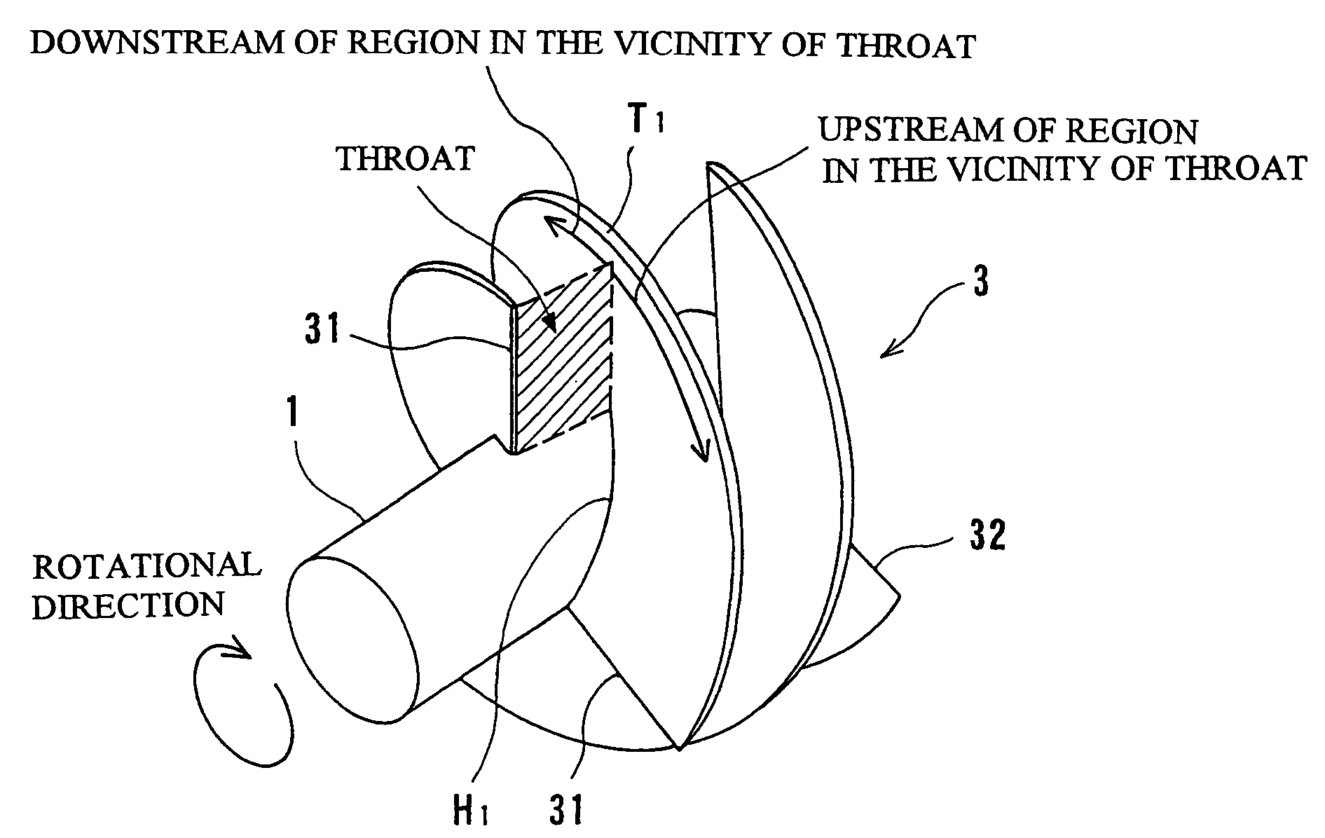
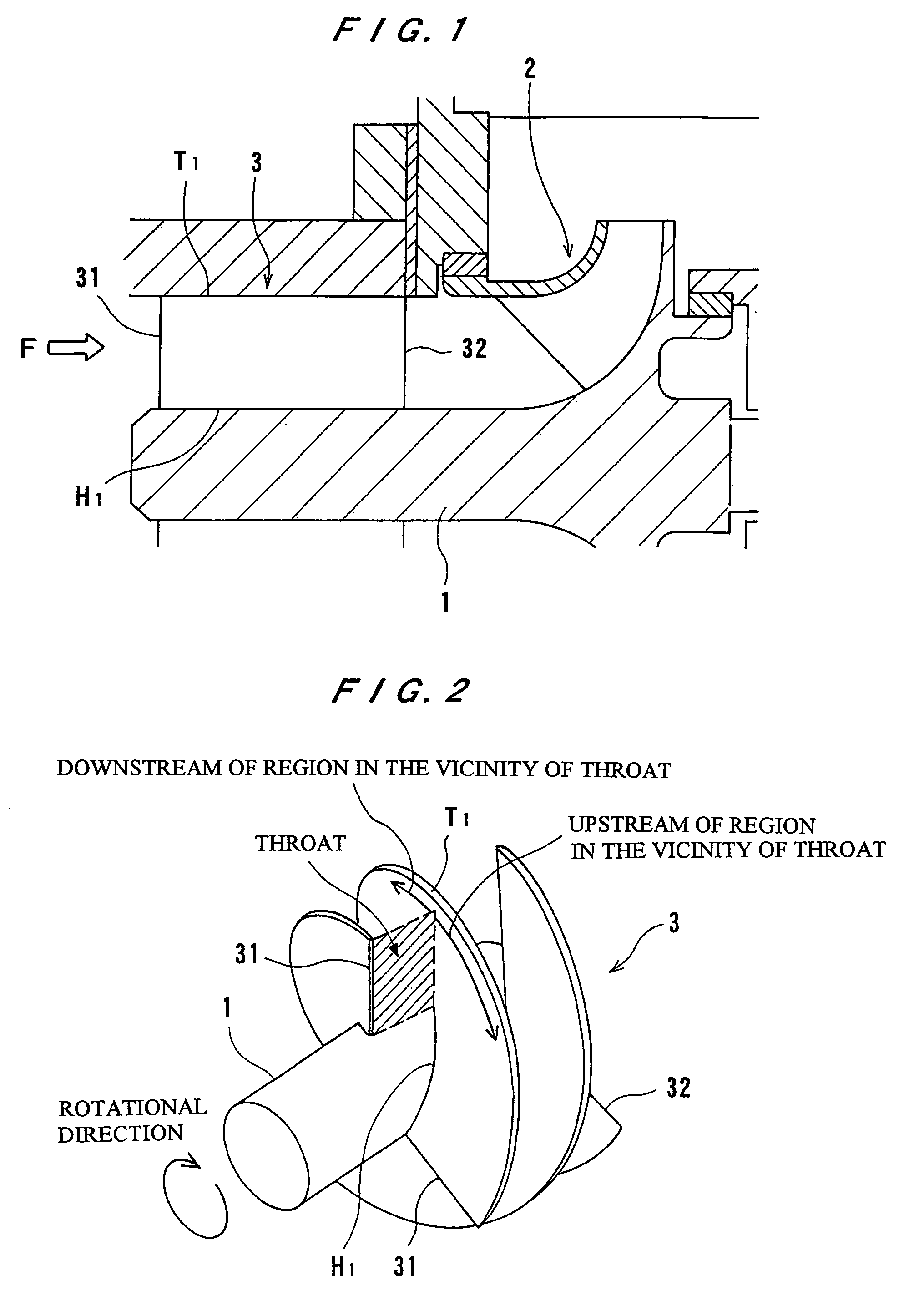
[0027]An embodiment of an inducer and a pump with an inducer according to the present invention will be described in detail below with reference to the drawings. FIG. 1 is a cross-sectional view showing a portion of a turbopump incorporating an inducer according to an embodiment of the present invention, and FIG. 2 is a perspective view of the inducer shown in FIG. 1. The turbopump shown in FIG. 1 has a rotatable shaft 1, a main impeller 2 mounted on the shaft 1, and an inducer 3 disposed upstream of the main impeller 2. The inducer 3 has an axis in alignment with the axis of the main impeller 2. When the shaft 1 rotates, the inducer 3 rotates at the same rotational speed as the main impeller 2. The inducer 3 has a plurality of blades. In FIG. 2, the inducer 3 is shown as having three blades.

[0028]A working fluid of the pump flows into the inducer 3 in the direction indicated by the arrow F in FIG. 1. The working fluid that has flowed into the inducer 3 has its pressure increased wh...


PUM


Abstract

The present invention is concerned with an axial-flow or mixed-flow inducer (3) which is disposed upstream of a main impeller (2) for improving the suction capability of a pump such as a turbopump. In the inducer (3), a blade angle (βbt) from a tip (T1) to a hub (H1) at a blade leading edge (31) is substantially the same as an inlet flow angle (β1−t) at a designed flow rate.

Description

TECHNICAL FIELD[0001]The present invention relates to an inducer and a pump with an inducer, and more particularly to an axial-flow or mixed-flow inducer which is disposed upstream of a main impeller with its axis aligned with an axis of the main impeller for improving the suction capability of a pump such as a turbopump, and a pump with such an inducer.BACKGROUND ART[0002]Heretofore, it has been customary to mount an inducer on the distal end of the shaft of a pump for improving the suction capability of the pump. For example, an inducer disposed upstream of a centrifugal main impeller comprises an axial-flow or mixed-flow impeller which has configurational characteristics in that it has less blades and a longer blade length than ordinary impellers. The inducer is disposed upstream of the main impeller with its rotational axis aligned with the main impeller, and is rotated by the shaft at the same rotational speed as the main impeller.[0003]Conventional inducers have blades designe...

Claims


Application Information

Patent Timeline
Patent Type & Authority Patents(United States)
IPC IPC(8): F04D29/18F04D29/66F04D29/22
CPCF04D29/2277
Inventor ASHIHARA, KOSUKEGOTO, AKIRA
Owner EBARA CORP
Learn More