
Two-piece tire

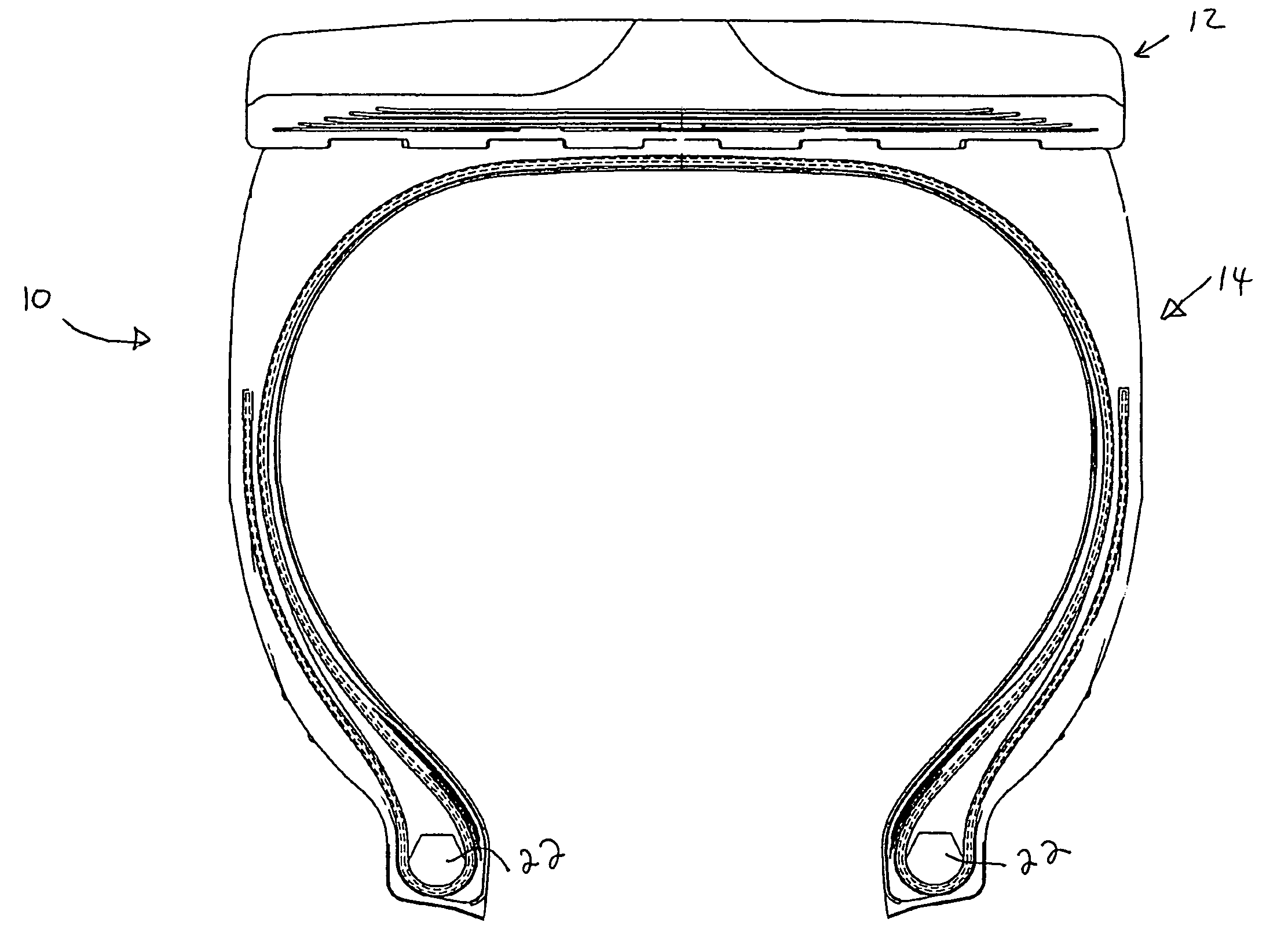
a pneumatic tire and tire body technology, applied in the field of two-piece pneumatic tires, can solve the problems of high stress and load, interface degradation,

Inactive Publication Date: 2007-04-24
THE GOODYEAR TIRE & RUBBER CO
View PDF14 Cites 9 Cited by
  • Summary
  • Abstract
  • Description
  • Claims
  • Application Information

AI Technical Summary

Benefits of technology

The self-lubricating composition reduces friction and improves abrasion resistance, extending the tire's lifespan and performance in high-stress environments.

Problems solved by technology

Two piece pneumatic tires having removable tread belts disposed over a tire carcass are generally designed for use on large earthmover vehicles and are subjected to high stress and loads under harsh environmental conditions such as in rock quarries, mines, foundries, and other areas where tires are subjected to puncture-producing and wear-inducing conditions.
In particular, the rubber interface between the tread belt and the carcass may be subject to movement between the tread belt and carcass, which may lead to degradation at the interface.

Method used


Image

  • Two-piece tire
  • Two-piece tire
  • Two-piece tire

Examples


example i

[0041]In this Example, a alcohol of formula I and an ester of formula II were evaluated in a rubber composition containing carbon black.

[0042]Rubber compositions containing the materials set out in Table 1 were prepared using four separate stages of addition (mixing); namely three non-productive mix stages and one productive mix stage. The non-productive stages were mixed for four minutes to a rubber temperature of 160° C. The productive stage was mixed for two minutes, and the drop temperature for the productive mix stage was 115° C.

[0043]The rubber compositions are identified as Sample A–H. Samples A, D, E and H are considered as controls due to the absence of the alcohol or ester.

[0044]The Samples were cured at about 150° C. for about 32 minutes.

[0045]Table 2 illustrates the physical properties of the cured Samples A through H.

[0046]The coefficient of friction (COF) test is done according to ASTM D-1894 on a Model SP-2000 Slip / Peel Tester from IMASS Inc. Samples are tested at 6 i...

example ii

[0050]In this Example, two amides of formula III were evaluated in a rubber composition containing carbon black.

[0051]Rubber compositions containing the materials set out in Table 3 were prepared using four separate stages of addition (mixing); namely three non-productive mix stages and one productive mix stage. The non-productive stages were mixed for four minutes to a rubber temperature of 160° C. The productive stage was mixed for two minutes, and the drop temperature for the productive mix stage was 115° C.

[0052]The rubber compositions are identified as Samples I-P. Samples I, L, M and P are considered as controls due to the absence of the amide.

[0053]The Samples were cured at about 150° C. for about 32 minutes.

[0054]Table 4 illustrates the physical properties of the cured Samples I through P.

[0055]The coefficient of friction (COF) test is done according to ASTM D-1894 on a Model SP-2000 Slip / Peel Tester from IMASS Inc. Samples are tested at 6 inches per minute using a 200 g sle...


PUM

PropertyMeasurementUnit
temperatureaaaaaaaaaa
melting pointaaaaaaaaaa
BET surface areaaaaaaaaaaa

Abstract

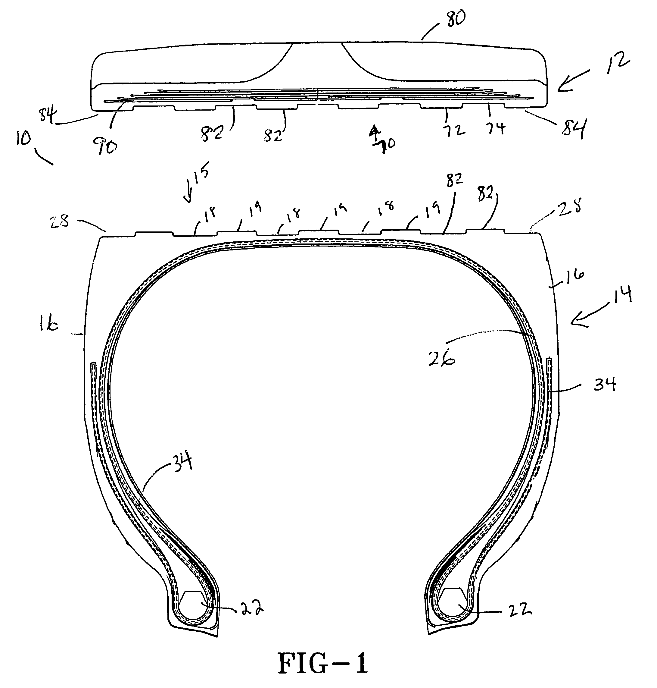
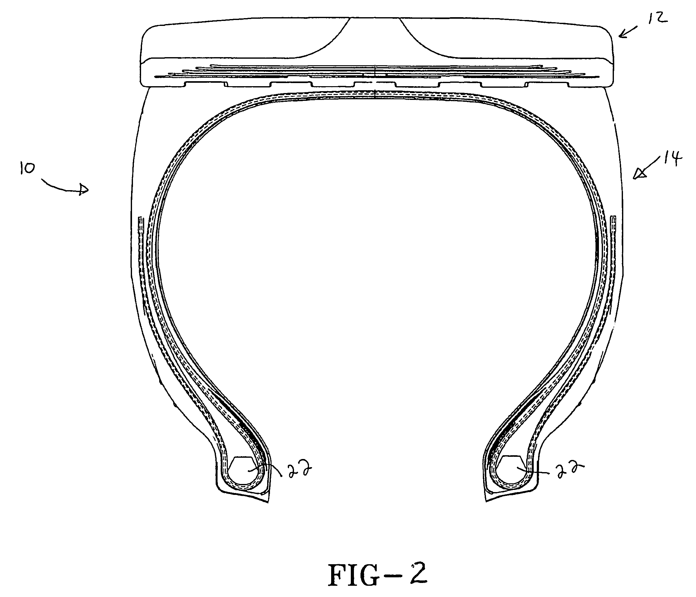
The present invention relates to a two piece pneumatic tire comprising a carcass and a removable tread belt disposed radially about the periphery of the carcass, the tread belt and carcass meeting at an interface between a radially outermost surface of the carcass and a radially innermost surface of the tread belt, wherein at least one of the radially outermost surface of the carcass and the radially innermost surface of the tread belt comprise a self lubricating rubber composition, the self lubricating rubber composition comprising at least one rubber and from 1 to 50 phr of at least one additive selected from alcohols of formula I, esters of formula II, or amides of formula IIIwherein R1 and R2 are independently selected from C12–C36 alkyl, C12–C36 alkenyl, or C12–C36 alkadienyl.

Description

BACKGROUND OF THE INVENTION[0001]Two piece pneumatic tires having removable tread belts disposed over a tire carcass are generally designed for use on large earthmover vehicles and are subjected to high stress and loads under harsh environmental conditions such as in rock quarries, mines, foundries, and other areas where tires are subjected to puncture-producing and wear-inducing conditions. In particular, the rubber interface between the tread belt and the carcass may be subject to movement between the tread belt and carcass, which may lead to degradation at the interface.SUMMARY OF THE INVENTION[0002]The present invention relates to a two piece pneumatic tire comprising a carcass and a removable tread belt disposed radially about the periphery of the carcass, the tread belt and carcass meeting at an interface between a radially outermost surface of the carcass and a radially innermost surface of the tread belt, wherein at least one of the radially outermost surface of the carcass ...

Claims


Application Information

Patent Timeline
Patent Type & Authority Patents(United States)
IPC IPC(8): B60C1/00B60C11/00B60C9/02
CPCB60C11/02C08K5/05C08K5/101C08K5/20C08K3/0025C08L21/00Y10T152/10495Y10T152/10855Y10T152/1081C08K3/012
Inventor SANDSTROM, PAUL HARRYSEGATTA, THOMAS JOSEPH
Owner THE GOODYEAR TIRE & RUBBER CO
Learn More