
Interchangeable gooseneck faucet

Inactive Publication Date: 2007-04-24
SPEAKMAN
View PDF21 Cites 19 Cited by
  • Summary
  • Abstract
  • Description
  • Claims
  • Application Information

AI Technical Summary

Benefits of technology

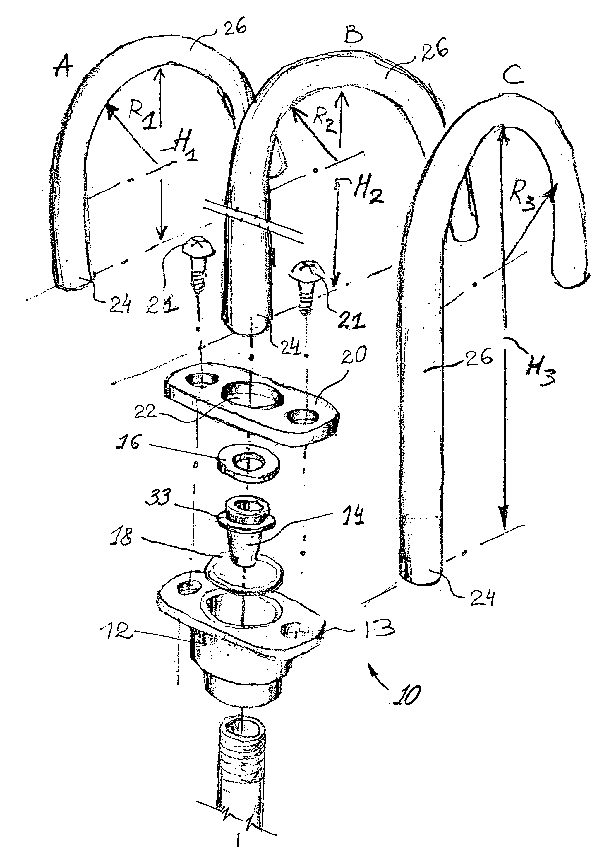
[0007]An object of the present invention is, therefore, a faucet spout assembly with easily interchangeable spouts.
[0008]Another object of the invention is to provide new methods of forming a laminar stream at the outlet of a spout while at the same time preventing accumulation of germs and dust around the apparatus providing the laminar flow
[0009]Still another object of the invention is to provide faucet spout assembly constructed of a minimal amount of parts, wherein each of them is simple and easy to assemble.
[0011]Still another object of the invention is to provide a sealing engagement of spout to faucet that provides an effective water-tight seal between these parts while accommodating slight dimensional variation among the spouts when positioned on the faucet.
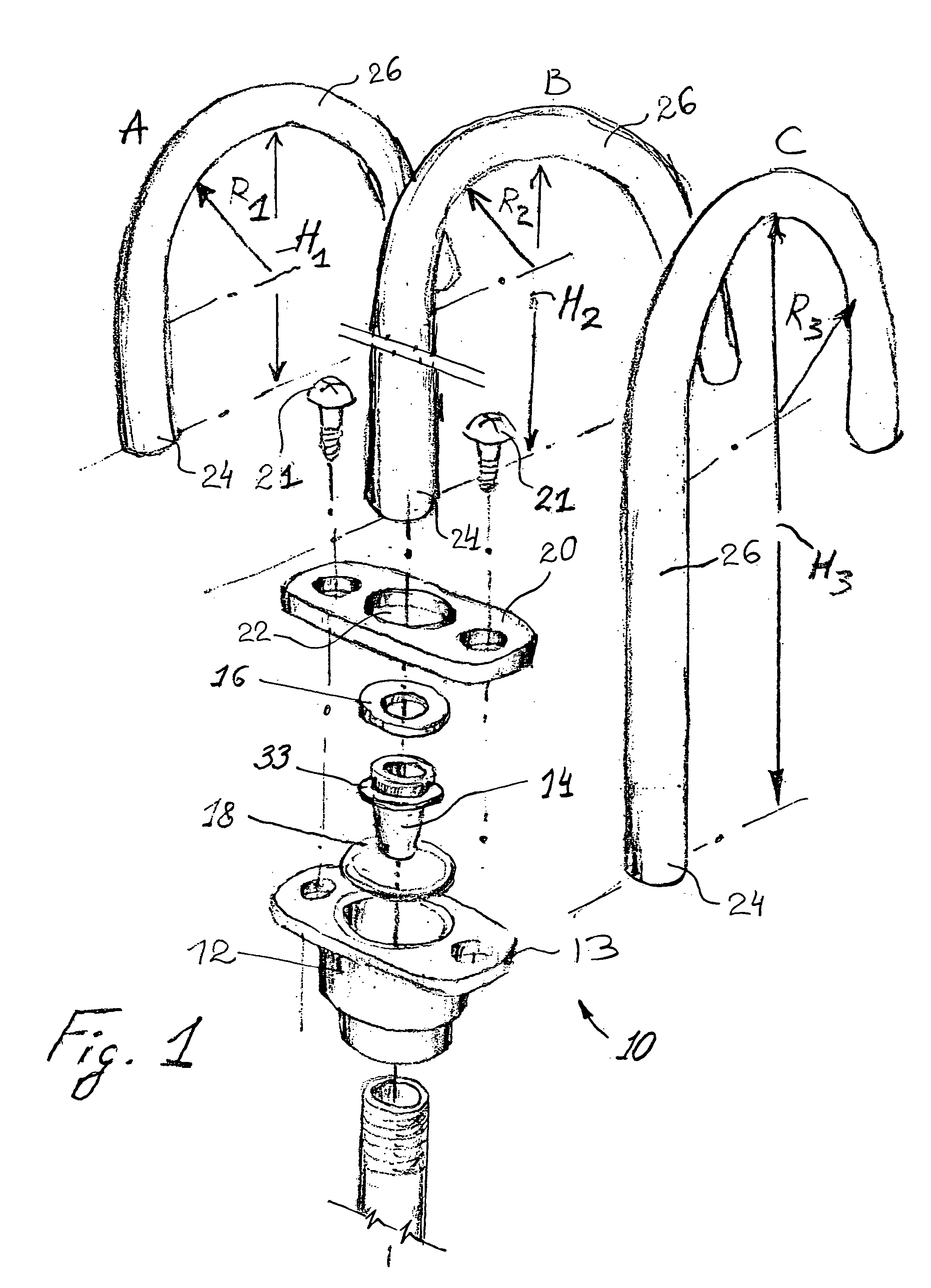
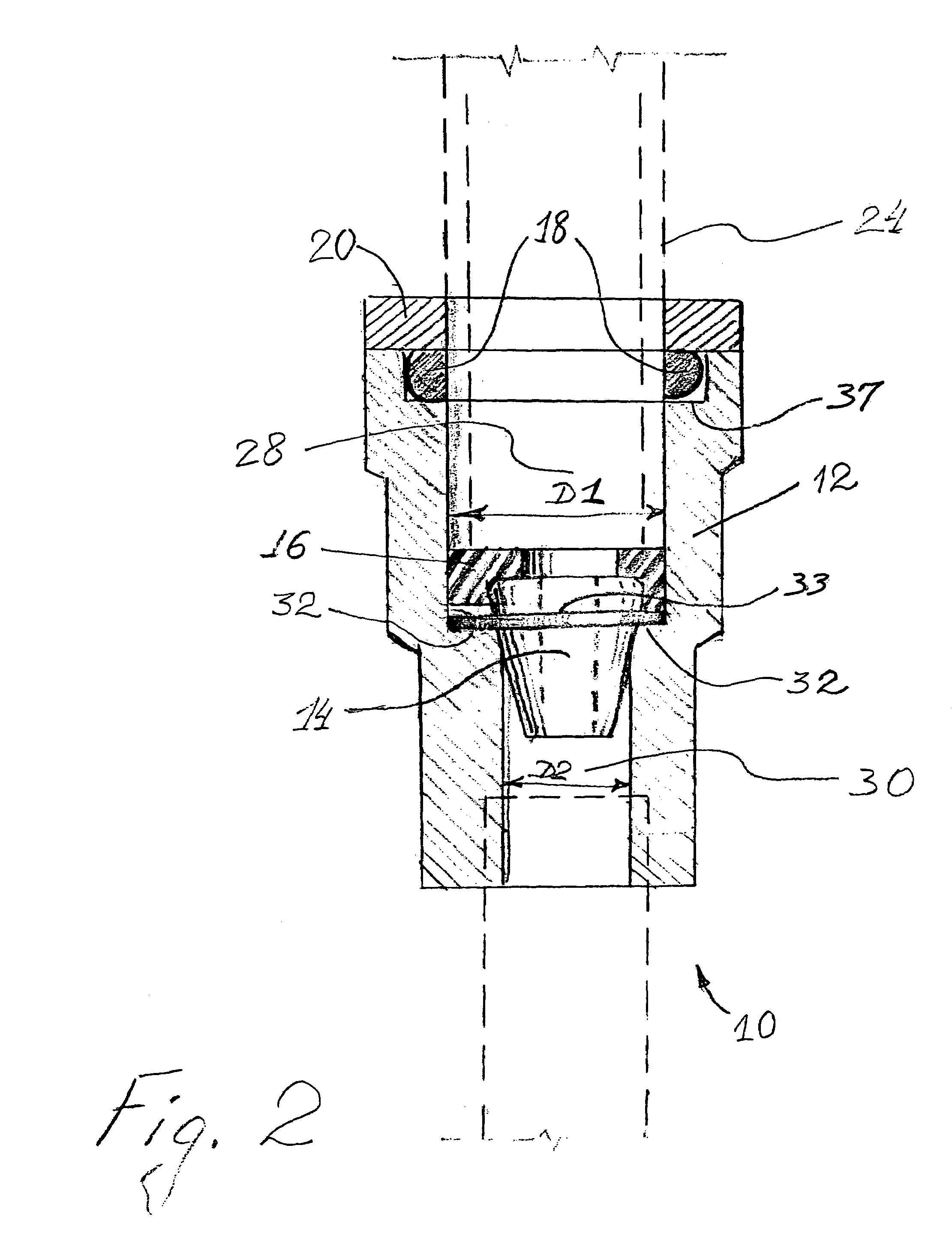
[0016]Other approaches to sealing the spout within the spout receptacle are also contemplated. More particularly, as more fully discussed below, it has been found advantageous to include a check valve in the upstream end of the interchangeable spout which fits into the spout receptacle A cylindrical check valve holder is sized to fit within that end of the spout The check valve holder is preferably cylindrical with a peripheral rim that is pressed into engagement with the flat washer at the bottom of the spout receptacle. This provides some additional sealing since the bottom surface of the check valve holder is greater, and flatter, than the bottom of the spout. This increased surface area in contact with the flat washer reduces the opportunity for leakage at this point (spout-flat washer interface) of the faucet spout assembly.
[0018]Replacing a spout in the faucet of this invention is a simple operation of releasing bolts, or any affixing element, from the mating flanges on the faucet and spout. To place a new spout into the faucet, it is enough to insert the inlet end thereof into the spout receptacle and reattach the bolts or other affixing element joining the flanges of the spout and spout receptacle. These are tightened until the spout is sealed in the spout receptacle.

Problems solved by technology

This raises a problem of how to economically achieve interchangeability of spouts
Moreover, each spout must be equipped with a special spout-mounting plate so interchangeability of spouts is expensive and requires a large parts inventory.
This patent describes a height adjustable spout with a spigot-clamping member that is used to sealingly locate the spout at the desired height on the faucet This apparatus, however, has the distinct disadvantage of having a clamp handle extending into the useable space over the basin.
This would not be commercially acceptable because of poor aesthetics and the collection of mold and bacteria on the clamp.
Another problem with commonly used spout assemblies is the location of outlet devices used to soften the flow of water out of the spout They are typically located at the outlet of the spout.
Such devices—aerators, flow regulators and stream straighteners which are sometimes collectively referred to as laminar flow devices—serve as a trap, and consequently collector, for various germs and dirt because of their location at the spout outlet This problem is particularly acute in hospitals and health care facilities which must be particularly wary of areas where viruses like staphylococcus can take hold At the same time, it is difficult to abandon such spout end attachments in most applications because most faucet users demand a soft, non-splashing flow of water from a faucet spout.

Method used


Image

  • Interchangeable gooseneck faucet
  • Interchangeable gooseneck faucet
  • Interchangeable gooseneck faucet

Examples


Embodiment Construction

[0036]With reference to the accompanying drawings, the readily interchangeable faucet spout assembly according to the present invention will be described.

[0037]Referring first to FIG. 5, the environment in which the invention is particularly useful is illustrated. The overall faucet spout assembly 10 of this invention is illustrated in this Figure. The faucet spout assembly 10 is connected to a water supply, not shown, through a solenoid valve 11 and interconnecting piping 15 although this illustrated piping is not essential to the operation of the faucet spout assembly. This piping 15 may be connected to a spout 24 by the means of a spout receptacle 12 with a flange 13 containing suitable openings therein for receipt of fasteners 21. The spout receptacle 12 or inlet to solenoid 11 may also contain a flow control device 14. The spout receptacle 12 may also contain sealing means such as a sealing washer 16 and / or sealing O-ring 18 therein (See FIG. 1). A flange 20 having axial openin...


PUM


Abstract

A faucet spout assembly providing multiple spouts with different heights and curvature which are interchangeable within the same faucet. Laminar flow from the spout is achieved with a flow control device upstream of the spout outlet A check valve is optionally used in the inlet to the spout to promote greater flexibility in placement of the flow control device within the assembly.

Description

CROSS-REFERENCE TO RELATED APPLICATION[0001]This application claims the benefit of prior filed provisional application No. 60 / 331,848 filed Nov. 20, 2001 entitled Interchangeable Gooseneck Faucet.TECHNICAL FIELD OF THE INVENTION[0002]This invention relates generally to a faucet spout assembly and more particularly to a faucet assembly with interchangeable spouts which provide laminar, non-splashing water flow without any stream regulating attachment at the outlet of the spoutBACKGROUND OF THE INVENTION[0003]Faucet spout assemblies are widely used in households, industry, scientific laboratories, hospitals, etc. It is desired in some settings that faucet spouts of different configurations be available for use with a single faucet fixture. This raises a problem of how to economically achieve interchangeability of spouts[0004]Others have approached this problem as follows. According to Baker U.S. Pat. No. 6,256,810 an easy connect and disconnect faucet spout assembly is disclosed which...

Claims


Application Information

Patent Timeline
IPC IPC(8): E03C1/04
CPCE03C1/0404E03C2001/0414
Inventor PETERSON, GRAHAM H.BOYER, MICHAEL W.
Owner SPEAKMAN
Learn More