
Reader application markup language schema

a markup language and application technology, applied in the field of radio frequency identification, can solve the problems of inability to correctly read bar codes, inconvenient and inconvenient use of conventional systems and or methodologies, and achieve the effect of facilitating the execution of rfid processes

Inactive Publication Date: 2007-04-17
MICROSOFT TECH LICENSING LLC
View PDF31 Cites 60 Cited by
  • Summary
  • Abstract
  • Description
  • Claims
  • Application Information

AI Technical Summary

Benefits of technology

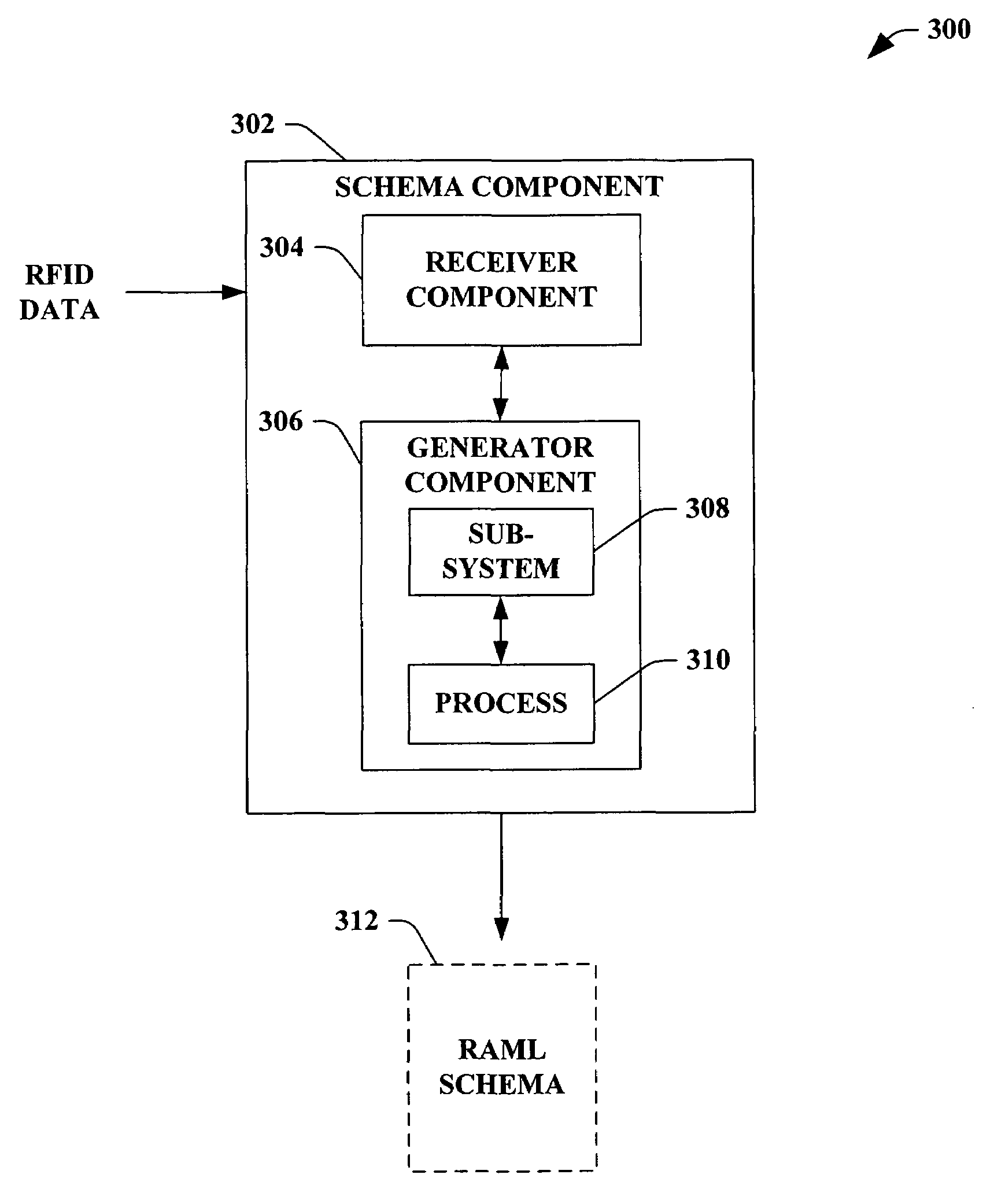
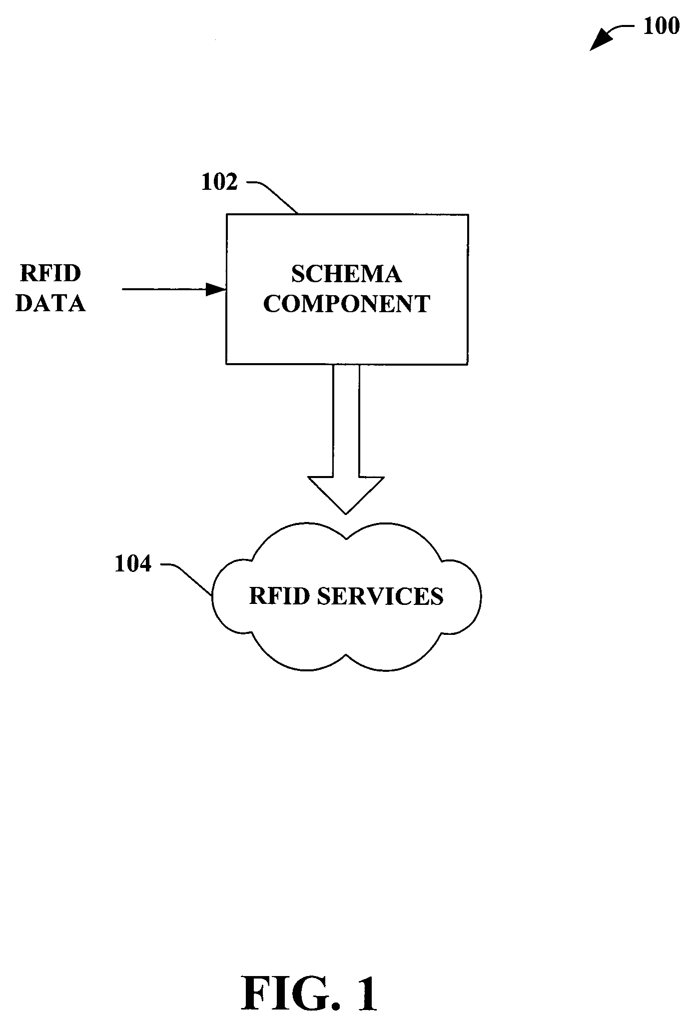
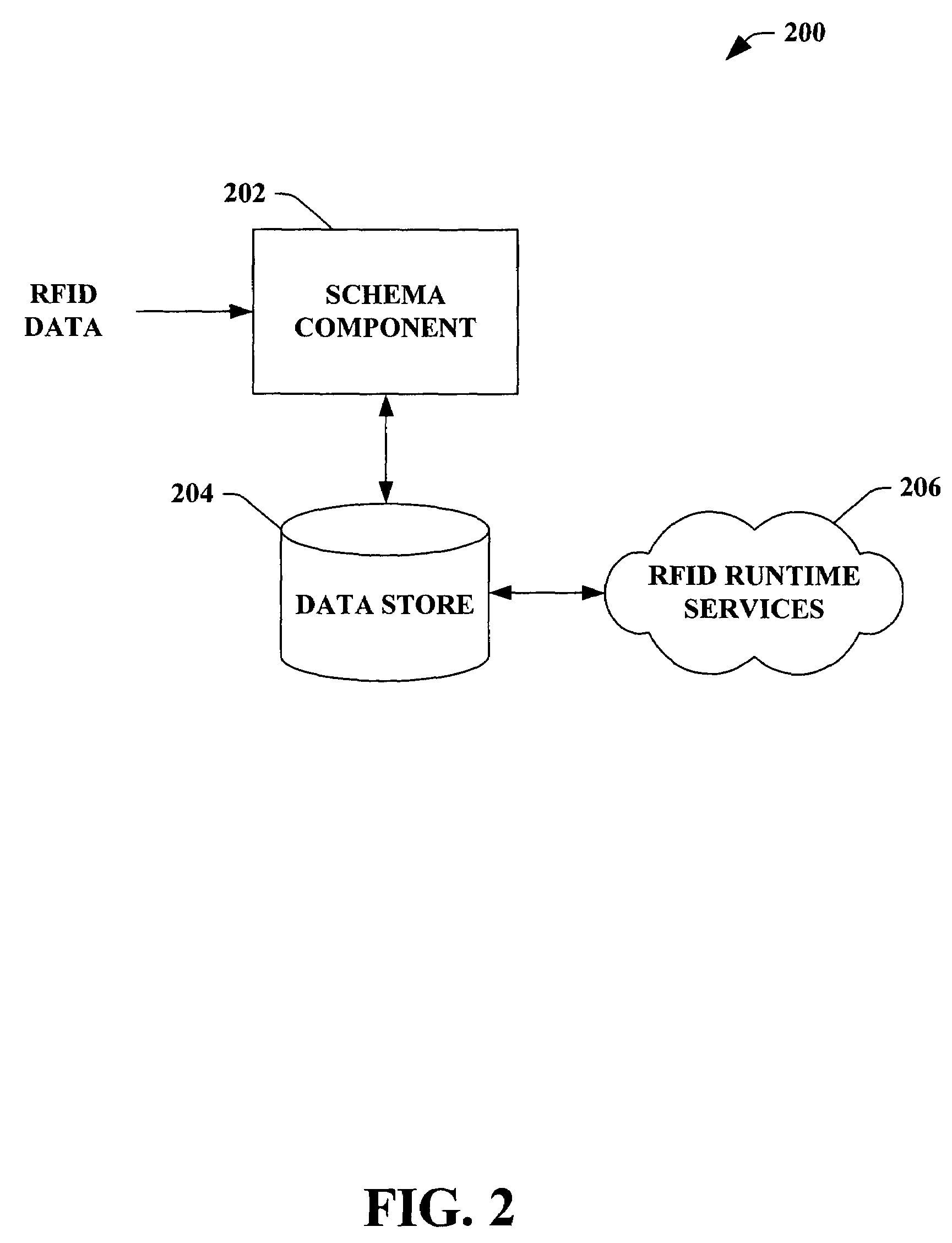
The invention is a system and method for executing RFID processes using a reader application markup language (RAML) schema. The RAML schema is created based on RFID data and includes a sub-system definition and a process definition. The RAML schema can be stored in a memory or data store for later use. The invention also includes a setup component that analyzes the RFID architecture to discover RFID readers and associated data, which is then used to create the RAML schema. The technical effect of the invention is to provide a portable format for setting up and deploying RFID processes, making it easier to execute RFID transactions.

Problems solved by technology

Such identifying information, however, is aesthetically displeasing as such information can clutter the product.
Moreover, tears, smudges, annotation or other physical damage / alteration to a barcode can render such conventional systems and or methodologies substantially useless.
If a portion of a bar code is torn from the product, a bar code scanner may not be able to correctly read the bar code.
Similarly, a smudge on a product can render such barcode unreadable.
In addition, the amount of information associated to the single barcode and / or UPC is limited.
Not only is the information insubstantial, but the information is not conducive to real-time product monitoring.
Yet, range is limited in RFID based upon radio frequency, RFID tag size, and associated power source.
In another example, RFID systems and / or methods can be implemented in water such as tracking and / or monitoring underwater pipe, whereas a barcode monitoring system presents numerous complications under such conditions.
Yet, the absence of the power supply limits the practical read range of the passive RFID tag from 10 mm to about 5 meters.

Method used


Image

  • Reader application markup language schema
  • Reader application markup language schema
  • Reader application markup language schema

Examples


Embodiment Construction

[0029]As utilized in this application, terms “component,”“system,” and the like are intended to refer to a computer-related entity, either hardware, software (e.g., in execution), and / or firmware. For example, a component can be a process running on a processor, a processor, an object, an executable, a program, and / or a computer. By way of illustration, both an application running on a server and the server can be a component. One or more components can reside within a process and a component can be localized on one computer and / or distributed between two or more computers.

[0030]The subject invention is described with reference to the drawings, wherein like reference numerals are used to refer to like elements throughout. In the following description, for purposes of explanation, numerous specific details are set forth in order to provide a thorough understanding of the subject invention. It may be evident, however, that the subject invention may be practiced without these specific ...


PUM


Abstract

The subject invention provides a system and / or method that facilitates executing a Radio Frequency Identification (RFID) process by employing a reader application markup language (RAML) schema that provides a portable format to setup and deploy such RFID process. A schema component can receive RFID data relating to an RFID architecture wherein a RAML schema can be created based at least upon such RFID data (e.g., discovered readers including settings and / or configurations). The RAML schema can include a sub-system definition (e.g., containing the definition of server state and entities in such server) and a process definition (e.g., containing process related entities and inter-relationships).

Description

CROSS-REFERENCE TO RELATED APPLICATION(S)[0001]This application claims the benefit of U.S. Provisional Patent Application Ser. No. 60 / 606,281 filed on Sep. 1, 2004, entitled “SYSTEM AND METHODS THAT FACILITATE RFID SERVER PROGRAMMING MODEL AND API'S,” and U.S. Provisional Patent Application Ser. No. 60 / 606,577 filed on Sep. 2, 2004, entitled “FACILITATE RFID SERVER PROGRAMMING MODEL AND API'S.” This application is also related to co-pending U.S. patent application Ser. Nos. 11 / 069,459, 11 / 061,356, and 11 / 061,337, filed on Mar. 1, 2005, Feb. 18, 2005 and Feb. 18, 2005, respectively. The entireties of these applications are incorporated herein by reference.TECHNICAL FIELD[0002]The subject invention generally relates to Radio Frequency Identification (RFID), and more particularly to a language schema to facilitate executing an RFID process associated with an RFID system and / or method.BACKGROUND OF THE INVENTION[0003]Many retail, manufacture, and distribution establishments are applying...

Claims


Application Information

Patent Timeline
Patent Type & Authority Patents(United States)
IPC IPC(8): G06F17/00G06K19/06
CPCG06Q10/08G06Q10/087Y10S707/99943G06Q50/10G06K17/00
Inventor KUMAR, ANUSHAHMED, MOHAMED FAKRUDEEN ALIGOTETI, JANAKI R.
Owner MICROSOFT TECH LICENSING LLC
Learn More