
System and method for function block execution order generation

Active Publication Date: 2007-04-03
ROCKWELL AUTOMATION TECH
View PDF7 Cites 30 Cited by
  • Summary
  • Abstract
  • Description
  • Claims
  • Application Information

AI Technical Summary

Benefits of technology

[0012]The following presents a simplified summary of the invention in order to provide a basic understanding of some aspects of the invention. This summary is not an extensive overview of the invention. It is intended neither to identify key or critical elements of the invention nor to delineate the scope of the invention. Its sole purpose is to present some concepts of the invention in a simplified form as a prelude to the more detailed description that is presented later. The invention provides methods and configuration systems by which the difficulties and disadvantages associated with manual function block ordering are eliminated or reduced. The invention further provides for improved data flow in control system routine execution, which allows the user to position function blocks in any position in a control system configuration system interface work surface, without adversely affecting data flow in the resulting control routine.
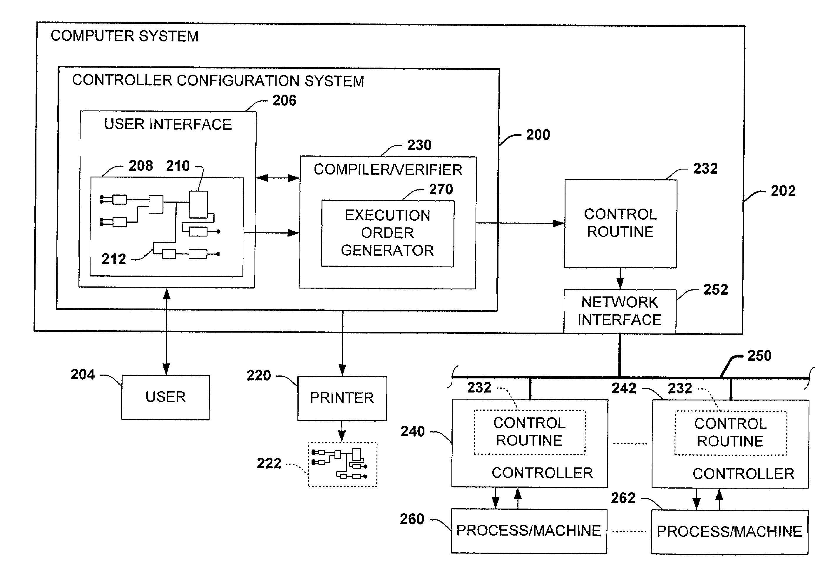
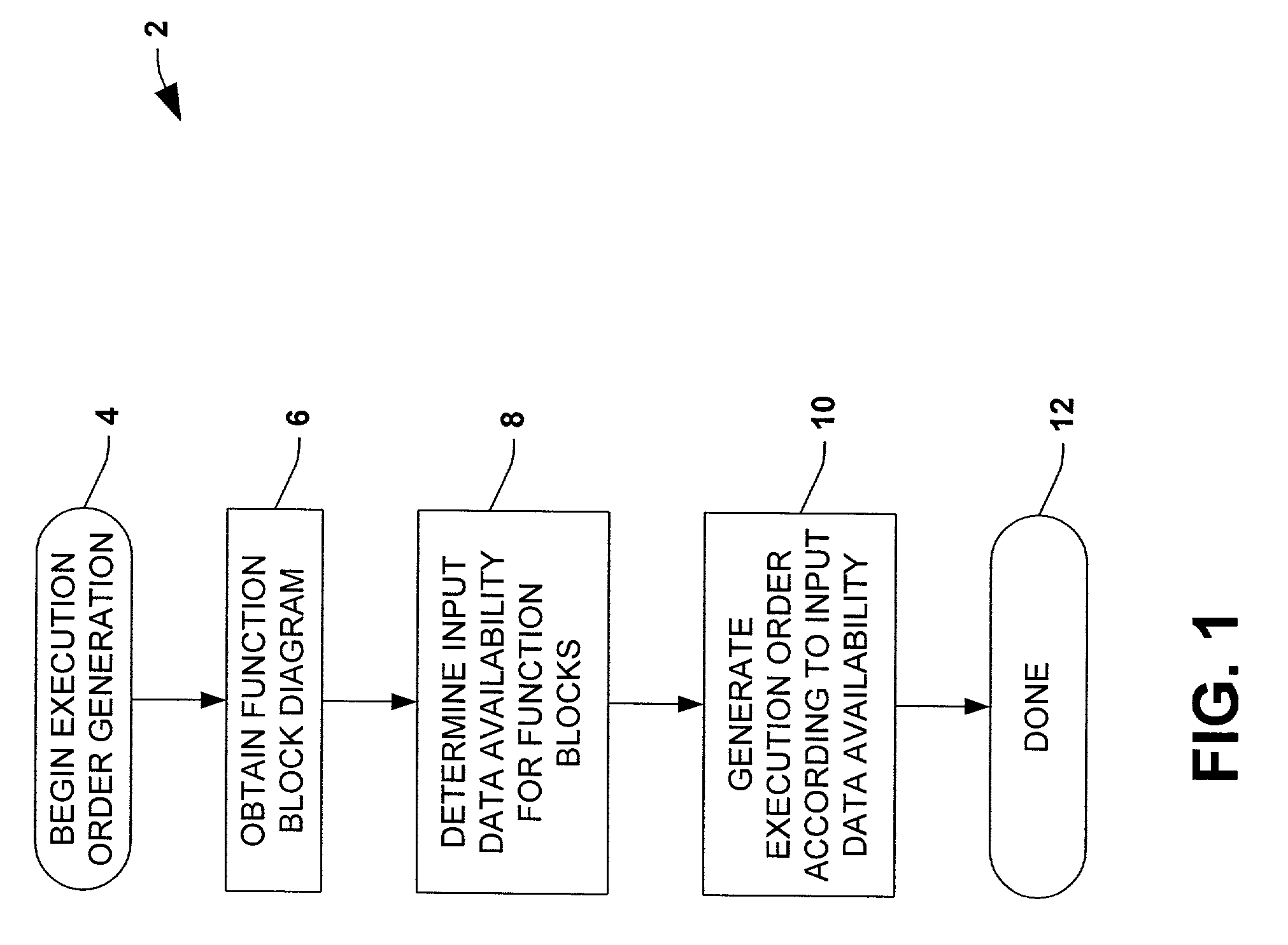
[0013]According to one aspect of the invention, a method is provided for generating an execution order for a function block diagram having a plurality of function blocks, wherein the function blocks each have one or more inputs. The method may be employed, for example, in a controller configuration system or tool, which translates or converts a function block diagram into a control program or routine for execution in a controller. The method comprises determining input data availability for the inputs of the plurality of function blocks, and generating an execution order for the function block diagram according to the input data availability for the inputs of the plurality of function blocks in the function block diagram. The invention thus provides for automatic function block execution ordering, which takes into account the availability of input data, whereby data flow problems are minimized or reduced. Moreover, the invention eliminates errors associated with manual execution ordering, and allows the user to focus on designing control strategies, rather than worrying about the location of function blocks in a function block diagram.

Problems solved by technology

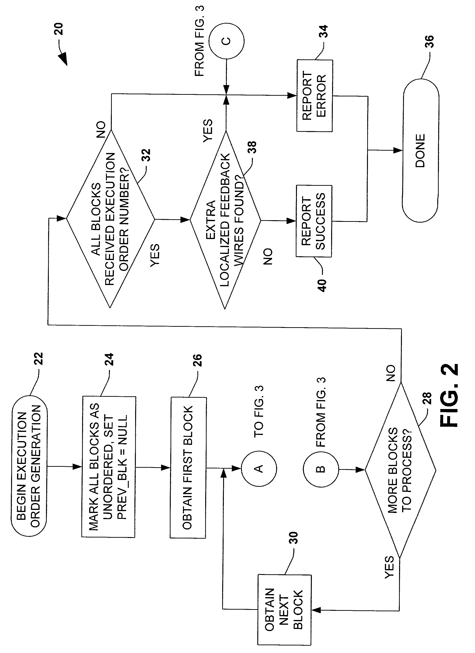
The method may further detect unspecified feedback loops in the function block diagram and generate a corresponding error, for instance, where no localized feedback wire exists in a feedback loop.

Method used


Image

  • System and method for function block execution order generation
  • System and method for function block execution order generation
  • System and method for function block execution order generation

Examples


Embodiment Construction

[0027]The various aspects of the present invention will now be described with reference to the drawings, wherein like reference numerals are used to refer to like elements throughout. The invention provides methods and systems for automatically generating an execution order for a control system function block diagram according to function block input data availability. The input data availability is determined for inputs of the function blocks in the diagram, and an execution order is generated for the function block diagram according to the input data availability for the function block inputs. The invention further includes methods and systems for generating a control routine from a function block diagram having a plurality of function blocks, wherein the control routine is generated from the function block diagram according to the execution order.

[0028]Referring now to the drawings, FIG. 1 illustrates an exemplary method 2 for generating an execution order for a function block di...


PUM


Abstract

Methods and systems are disclosed for automatically generating an execution order for a control system function block diagram. The input data availability is determined for the inputs of the function blocks in the diagram, and an execution order is generated for the function block diagram according to the input data availability for the function block inputs. Also disclosed are methods and systems for generating a control routine from a function block diagram having a plurality of function blocks, wherein the control routine is generated from the function block diagram according to the execution order.

Description

CROSS REFERENCE TO RELATED APPLICATIONS[0001]The present application claims the benefit of U.S. Provisional Patent Application Ser. No. 60 / 333,576, filed Nov. 27, 2001, entitled SYSTEM AND METHOD FOR FUNCTION BLOCK EXECUTION ORDER GENERATION.TECHNICAL FIELD[0002]The present invention relates to the art of industrial control systems, and more particularly to systems and methods for function block execution order generation.BACKGROUND OF THE INVENTION[0003]Industrial controllers are special purpose processing devices used for controlling industrial processes, machines, manufacturing equipment, and other factory automation applications. In accordance with a control program or routine, an industrial controller may measure one or more process variables or inputs representative of the status of a controlled process, and change outputs effecting control of the process. The inputs and outputs may be binary, (e.g., on or off), and / or analog assuming a continuous range of values. The control ...

Claims


Application Information

Patent Timeline
IPC IPC(8): G05B11/01G05B15/00G05B19/42G06F17/00G06F3/00G06F9/00G06F9/44G05B13/02G05B19/042G05B19/05G05B19/414G05B19/4155
CPCG05B19/0426G05B19/056G05B2219/13107G05B2219/13134G05B2219/25067
Inventor CACHAT, ANTHONY J.HEINEKING, UNNI M.SILVESTRO, MICHAELBAKER, JACOB S.JOHNSON, HOLLY E.REICHARD, DOUGLAS J.KNEZ, CAROL A.
Owner ROCKWELL AUTOMATION TECH
Learn More