
Image-based modeling and photo editing

Active Publication Date: 2007-04-03
SMARTER SYST INC
View PDF29 Cites 121 Cited by
  • Summary
  • Abstract
  • Description
  • Claims
  • Application Information

AI Technical Summary

Benefits of technology

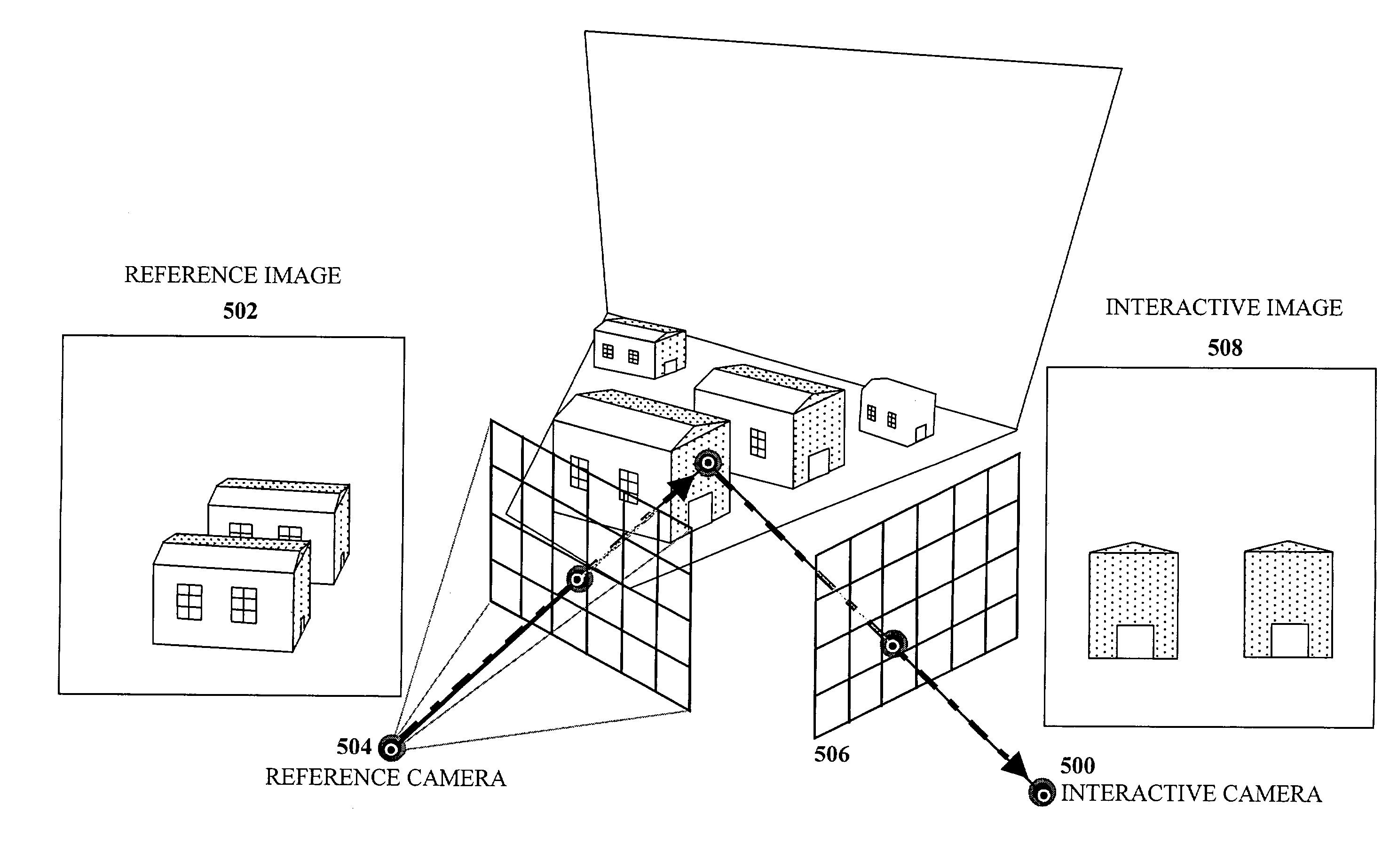
[0014]In another aspect, the invention provides a method of interactively editing an image containing depth information and reference camera information. The method includes steps of displaying the image from a viewpoint defined by an interactive camera, receiving an edit to the image, transforming the edit to a viewpoint defined by the reference camera, and applying the transformed edit to the image. In this way, a user can edit an image from an interactive viewpoint, and the results of editing the image may be kept in a structure having a viewpoint defined by a reference camera.
[0025]In some embodiments, transforming the image occurs substantially concurrently with a user identifying the destination region. In these embodiments, transforming the image may involve computing a parameterization only for selected “active pixels” substantially concurrently with the user identifying the destination region. In this manner, “clone brushing” can maintain a level of performance that permits interactive use.

Problems solved by technology

In some cases, this is achieved by using techniques that provide visually compelling results, which are not necessarily completely physically accurate.

Method used


Image

  • Image-based modeling and photo editing
  • Image-based modeling and photo editing
  • Image-based modeling and photo editing

Examples


Embodiment Construction

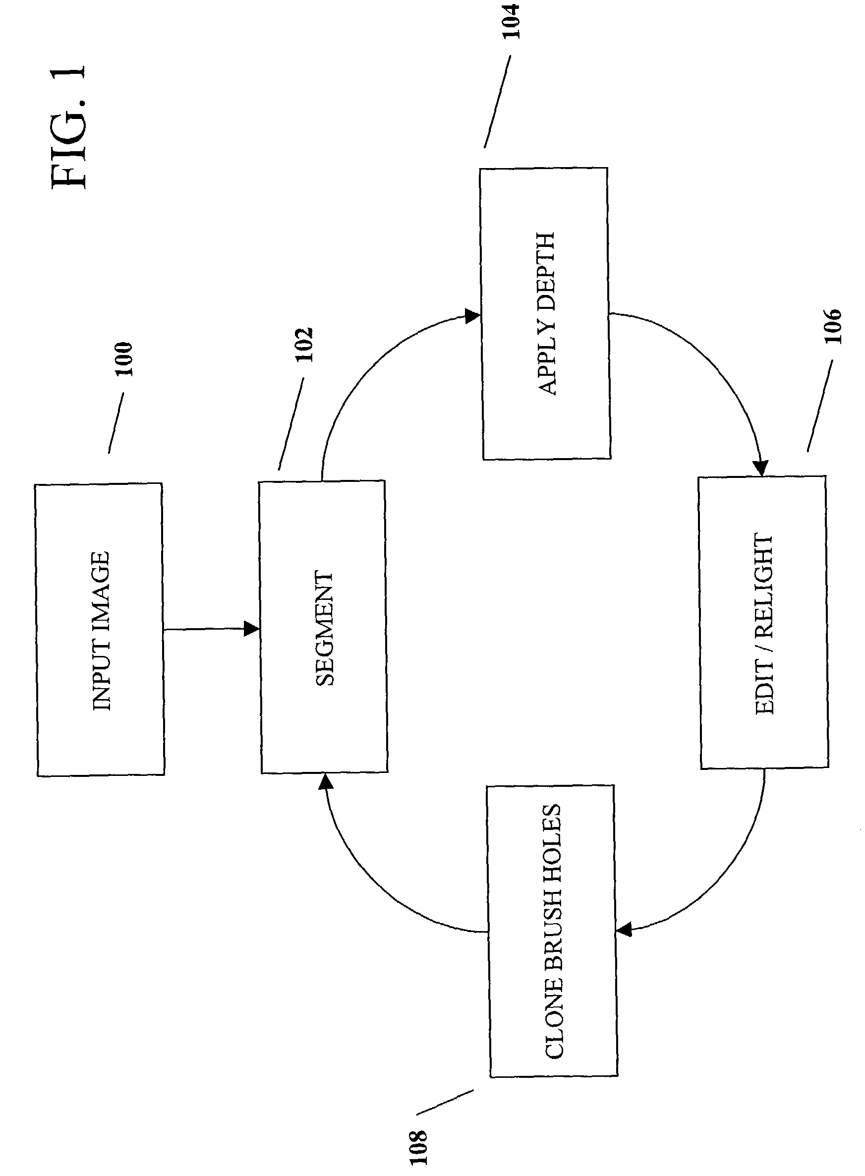
[0055]FIG. 1 illustrates a process to create and edit a three-dimensional (3D) image from an inputted two-dimensional (2D) image in accordance with the invention. A 3D image represents a three-dimensional scene, but may be displayed to a user as a 2D image on, for example, a computer monitor. In a preferred embodiment, the process begins by inputting into a computer system a two-dimensional image in an input image step 100. Alternatively, the computer system can accept for editing a 3D image which already has some depth information. Such 3D images may be acquired from a variety of laser, optical, or other depth measuring techniques for a given field of view. The image may be input by way of a scanner, electronic transfer, via a computer-attached digital camera, or other suitable input mechanism. Once the two-dimensional image has been input into the computer system, a user may begin to transform the image into a three-dimensional image by segmenting the two-dimensional image into la...


PUM


Abstract

The invention provides a variety of tools and techniques for adding depth information to photographic images, and for editing and manipulating images that include depth information. The tools for working with such images include tools for “painting” in a depth channel, for using geometric primitives and other three-dimensional shapes to define depth in a two-dimensional image, and tools for “clone brushing” portions of an image with depth information while taking the depth information and lighting into account when copying from one portion of the image to another. The tools also include relighting tools that separate illumination information from texture information.

Description

CROSS-REFERENCE TO RELATED APPLICATIONS[0001]This application claims the benefit of U.S. Provisional Application No. 60 / 382,259, entitled “Image-Based Modeling and Photo Editing”, filed May 21, 2002.FIELD OF INVENTION[0002]The invention relates generally to computer graphics. More specifically, the invention relates to a system and methods for editing images that include depth information.BACKGROUND[0003]An objective in the field of computer graphics is to recreate realistic images of three-dimensional environments using a computer. These images and the models used to generate them have an incredible variety of applications, from movies, games, and other entertainment applications, to architecture, city planning, design, teaching, medicine, and many others.[0004]Traditional techniques in computer graphics attempt to create realistic scenes using geometric modeling, reflection and material modeling, light transport simulation, and perceptual modeling. Despite the tremendous advances ...

Claims


Application Information

Patent Timeline
IPC IPC(8): G06T15/00G06T15/20G09G5/02
CPCG06T15/205
Inventor OH, BYONG MOKDURAND, FREDOCHEN, MAX
Owner SMARTER SYST INC
Learn More