Inductive lighting system with back-up battery

a technology of inductive lighting and backup battery, which is applied in the direction of lighting and heating apparatus, electric variable regulation, lighting applications, etc., can solve the problems of failure of the pathway system from the point of breach, many potential failure points in the prior art, and failure of the pathway system

Inactive Publication Date: 2007-04-03
GDRC
View PDF14 Cites 14 Cited by
  • Summary
  • Abstract
  • Description
  • Claims
  • Application Information

AI Technical Summary

Benefits of technology

[0005]The object of the present invention

Problems solved by technology

However, the prior art has many potential failure points.
The presence of water in the central power supply, containing the emergency battery back-up could cause the back-up to short circuit, resulting in a complete failure of the pathway system.
If either the electrical supply line fr

Method used


Image

  • Inductive lighting system with back-up battery
  • Inductive lighting system with back-up battery
  • Inductive lighting system with back-up battery

Examples


Embodiment Construction

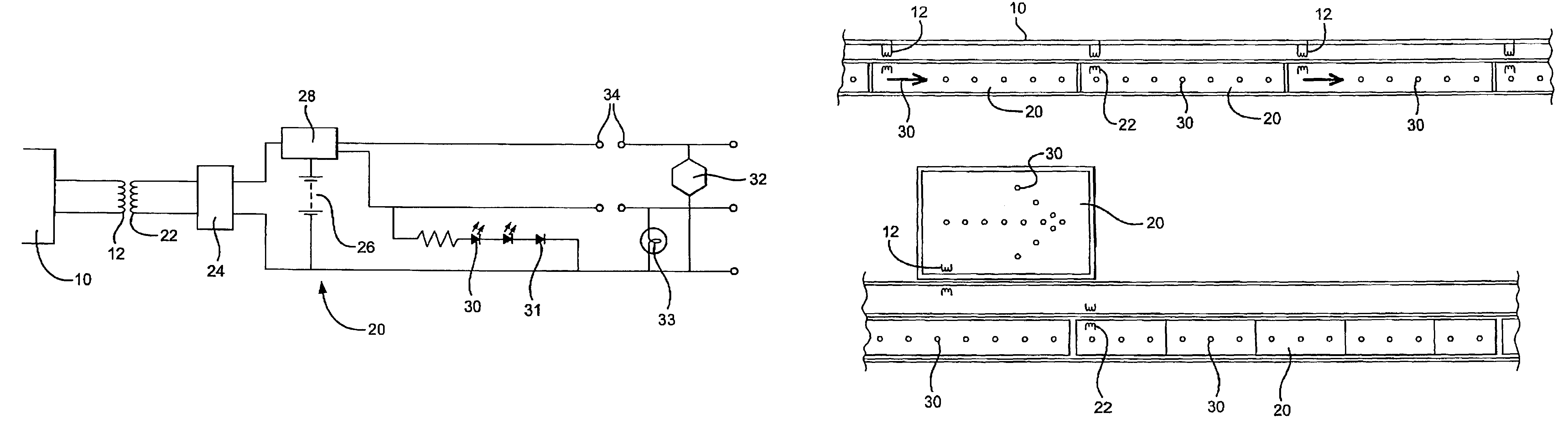
[0037]Referring to the drawings, FIG. 1 shows the lighting system of the invention 1. A carrier 10 is provided for supplying mains electricity 11 to the system 1. Positioned along the carrier are primary coils 12. The primary coils are fully encapsulated in the carrier and as such cannot be adversely Affected by on influx of water, for example during an emergency. The carrier is made from a suitable thermoplastic such as polycarbonate or polyproplyene.

[0038]The system also includes lighting modules 20. The modules 20 include secondary coils 22 which electro-magnetically link to the primary coils 12 for inducing electricity flow in the lighting modules 20. Battery back up 26 is also provided in the modules 20. The carrier assembly also includes voltage-conditioning circuitry 14.

[0039]The lighting modules 20 are designed to be sealed units to prevent the ingress of water or noxious gases that may cause failure of the circuitry. Thus, if the mains electricity fails, the lighting module...


PUM


Abstract

A pathway lighting system has self-contained, battery up scaled lighting modules (20), each module including at least one secondary coil. A plurality of primary coils are housed within a carrier assembly (1) together with voltage circuitry (14). Primary and secondary coils, positioned in the carrier assembly and in the lighting modules and the respectively allow electricity to flow between these members. The secondary coil output voltage is able to be rectified with the use of a rectification circuit, housed in the lighting module. Upon a mains failure, a battery charger/changeover circuit would switch the power requirements of the light sources inside the pathway lighting module over to internal back up batteries.

Description

CROSS-REFERENCE TO RELATED APPLICATIONS[0001]This application is for entry into the U.S. national phase under §371 for International Application No. PCT / GB03 / 00837 having an international filing date of Feb. 28, 2003, and from which priority is claimed under all applicable sections of Title 35 of the United States Code including, but not limited to, Sections 120, 363 and 365(c), and which in turn claims priority under 35 U.S.C. §119 to Great Britain Patent Application No. 0206798.1 filed on Mar. 22, 2002.TECHNICAL FIELD[0002]The present invention relates to lighting system, particularly though not exclusively for use in emergency pathways.BACKGROUND OF THE INVENTION[0003]Existing emergency pathway lighting systems typically consist of a linear system whereby one section of pathway lighting supplies power to the next section. The creation of an illuminated pathway is therefore reliant on links between pathway modules. Generally, printed circuit boards, housed in pathway modules, adjo...

Claims


Application Information

Patent Timeline
IPC IPC(8): H05B41/16F21S8/04F21S9/02F21Y101/02H02J7/34H02J9/00H02J9/02H02J9/06H05B37/02H05B41/14
CPCF21S9/022G08B7/066H02J9/065H05B33/0803F21W2111/027F21W2111/08F21Y2101/02F21Y2115/10H05B45/30
Inventor VERNON-DIER, DAVID RICHARD
Owner GDRC
Why Eureka
Try Eureka