Method for producing an adhesive closing element

a technology of closing element and adhesive, which is applied in the field of production of adhesive closing element, can solve the problems of high adhesive force and inability to clear

Inactive Publication Date: 2007-04-03
GOTTLIEB BINDER
View PDF11 Cites 133 Cited by
  • Summary
  • Abstract
  • Description
  • Claims
  • Application Information

AI Technical Summary

Benefits of technology

[0005]Objects of the present invention are to provide an improved process such that good ejection of the interlocking means, after the shaping process, is achieved, even at very high production rates, and such that the interlocking means produced in this way leads to closing parts which adhere well and which can be joined to one another.
[0006]These objects are attained by the present invention, where at least in the lengthwise section of the respective mold cavity, the opposing boundary walls are provided with a continuously convex path. A continuously extending transition is achieved between the cross sectional shapes of the stem part and the head part for the interlocking means of the backing. This continuous transition along the convex path then leads essentially to unimpeded mold removal process without the danger of the head parts tearing off from their assigned stem part over sharp-edged shape transitions. Moreover, head parts can be formed with a height which decreases toward their outer peripheral edge such that a type of interlocking lip is formed. In this manner, the head parts are elastically very flexible on the edge side and are easy interlocked to one another or with an assigned loop material. With the pertinent fitting of interlocking means of one type into the intermediate spaces of the interlocking means of another or same type, the lips of the head parts are pushed elastically aside, to immediately re-assume their original position after engaging and to block the initially cleared intermediate space again. In this way, very favorable closing behavior between the two adhesive closing parts which form a closure is possible.

Problems solved by technology

When the backing with the interlocking means is removed from the mold, these high adhesive forces can lead at least in part even to tearing off of the molded head part when the process sequence is not adjusted precisely.
This forming leads to difficulties if, for example, the head parts of the same type are to fit into the respective intermediate spaces of the interlocking means of another closing part, which spaces have been left open, to produce a complete closure.
These intermediate spaces are not cleared first of all as desired for the interlocking due to the rigidity of the interlocking means.

Method used


Image

  • Method for producing an adhesive closing element
  • Method for producing an adhesive closing element
  • Method for producing an adhesive closing element

Examples


Embodiment Construction

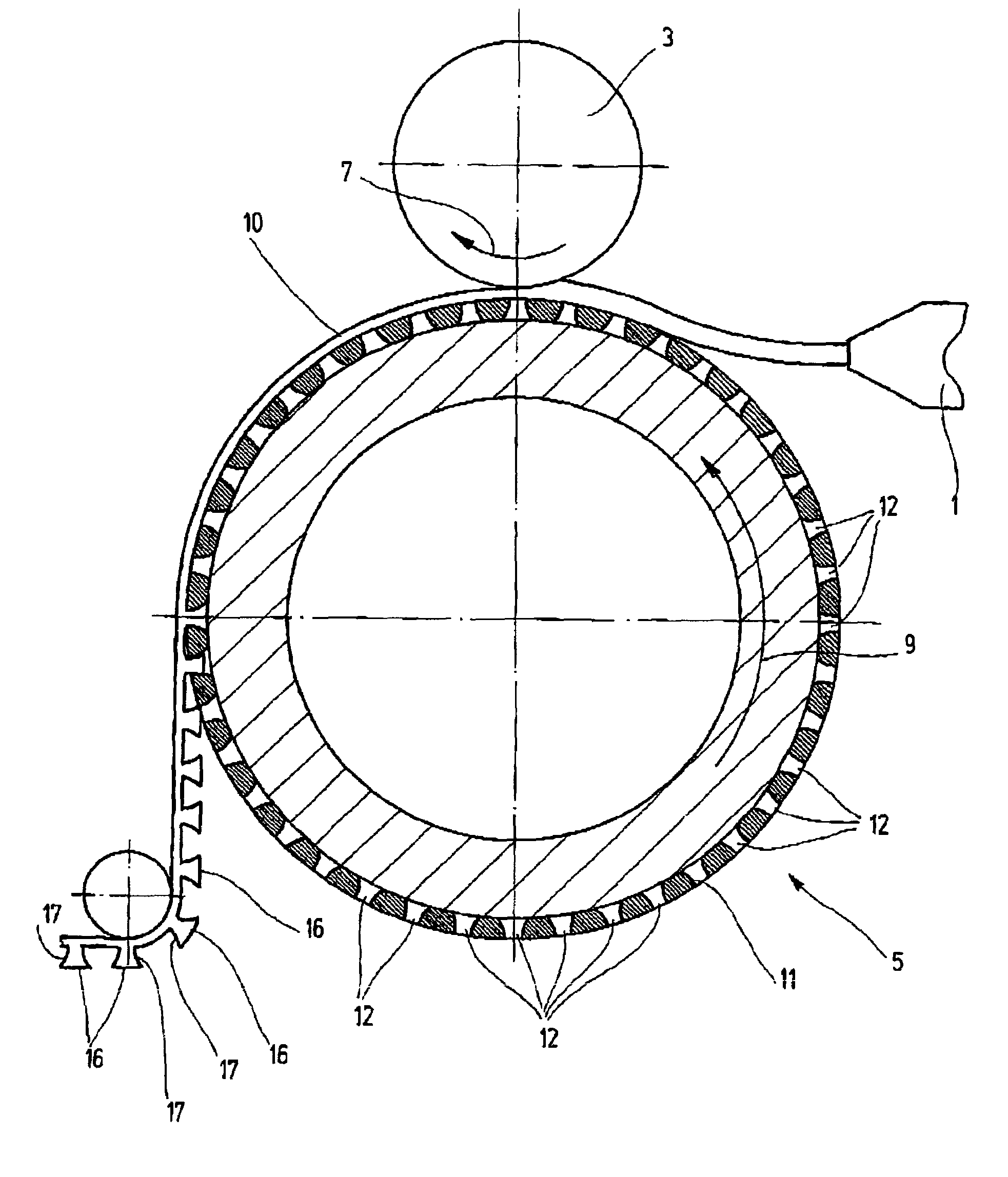
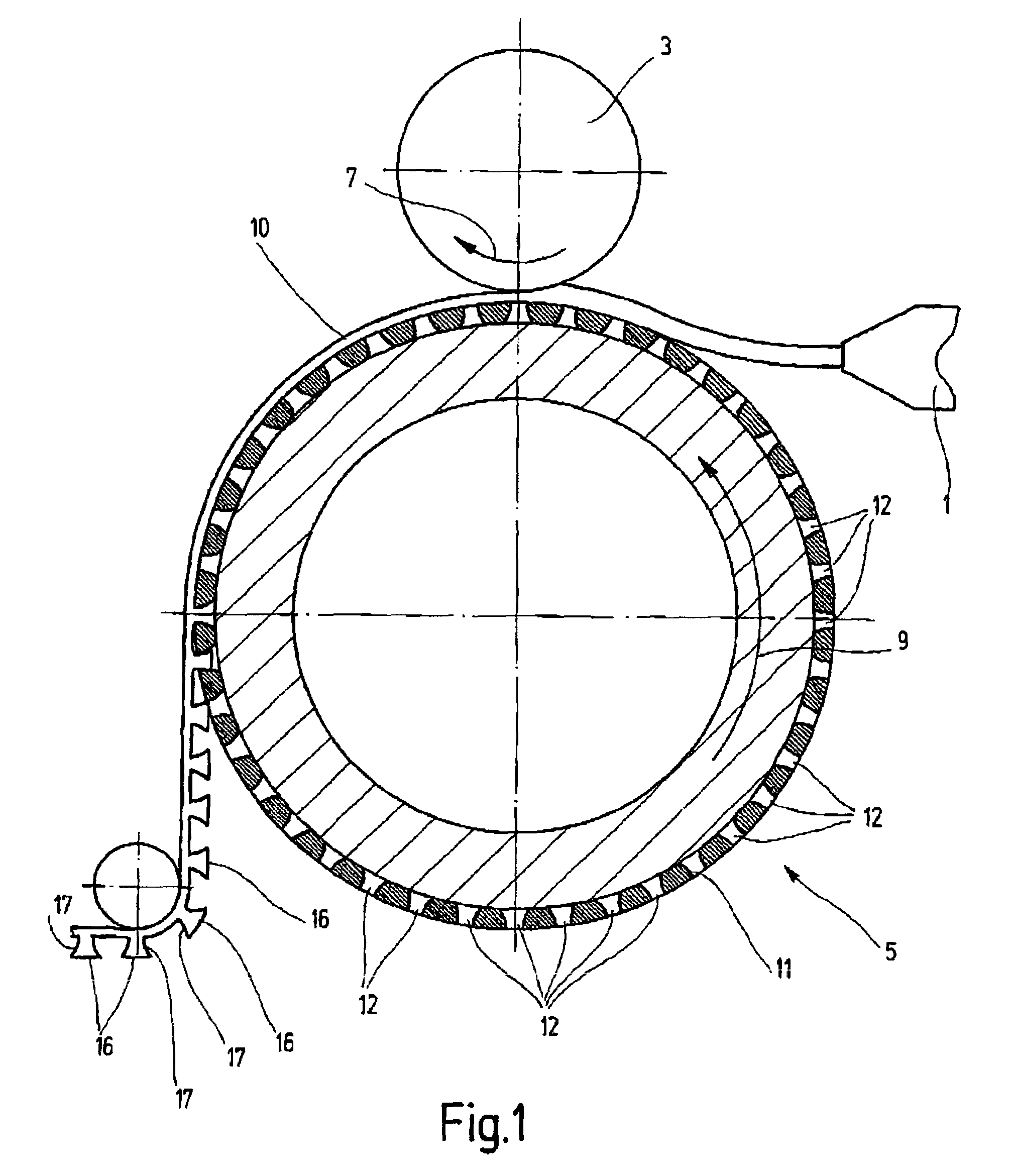
[0020]FIG. 1 schematically shows parts of a device for implementing a process according to an embodiment of the present invention. An extruder head 1 operates as the feed means for a plastic in a plastic or liquid state, especially a thermoplastic. The plastic is supplied to the gap between the pressure tool and a molding tool as a strip with a width corresponding to that of the adhesive closing part which is to be produced. The pressure tool is a pressure roller 3. The molding tool is a mold roller, designated as 5 in its entirety. The two rollers are driven in the directions of rotation shown in FIG. 1 by curved arrows 7 and 9. Between the rollers, a conveyor gap is formed through which the plastic strip is conveyed in the transport direction. At the same time in the gap forming the shaping zone, the plastic strip is molded into the backing 10 of the adhesive closing part. The backing 10 acquires the shape necessary for forming the interlocking means on the side adjacent to the mo...


PUM

PropertyMeasurementUnit
widthaaaaaaaaaa
widthaaaaaaaaaa
widthaaaaaaaaaa

Abstract

A process for produces an adhesive closing element including a plurality of hook elements connected to a backing (10) forming a single piece with the hook elements and being disposed symmetrically thereon. The hook elements are provided in the form of a stem component (17) having a head piece (16). A deformable material is introduced into a forming zone in between a production master (3) and a forming tool (5). The opposite-lying defining walls, at least when seen in a longitudinal section of the respective forming cavity (12), are provided with a continuous convex trajectory. A continuous transition between the cross-sectional forms of the stem component (17) and the head piece (16) is provided for a hooking of the backing (10) resulting in seamless removal.

Description

FIELD OF THE INVENTION[0001]The present invention relates to a process for producing an adhesive closing part with a plurality of interlocking means having a symmetrical structure and connected integrally to a backing. The interlocking means are in the form of a stem part provided with a head part. A moldable material is supplied to the shaping zone between a pressure tool and a molding tool driven such that the backing is formed in the shaping zone and conveyed in the transport direction. Mold cavities with boundary walls opposite one another are used as the shaping element on the molding tool.BACKGROUND OF THE INVENTION[0002]WO 00 / 00053 A1 discloses a generic process for producing an adhesive closing part with a plurality of interlocking means formed integrally with a backing. The interlocking means are in the form of stems which have end-side thickened areas. A moldable plastic material in the plastic or liquid state is supplied to the gap between a pressure roller and a mold rol...

Claims


Application Information

Patent Timeline
Patent Type & Authority Patents(United States)
IPC IPC(8): B29C47/00A44B18/00B29C43/22B29C43/24B29C43/46B29C48/07B29C48/08B29C48/35
CPCA44B18/0049B29C43/222B29C47/0021B29C43/46B29C47/32B29C2043/461B29L2031/729B29C48/08B29C48/35A44B18/00
Inventor TUMA, JAN
Owner GOTTLIEB BINDER
Why Eureka
Try Eureka