
Down-the-hole drill assembly

a drill assembly and drill bit technology, applied in the direction of instruments, fluid removal, portable percussive tools, etc., can solve the problems of reducing affecting the performance of the hammer, and weakening the walls of the piston

Active Publication Date: 2007-04-03
GIEN BERNARD LIONEL
View PDF4 Cites 10 Cited by
  • Summary
  • Abstract
  • Description
  • Claims
  • Application Information

AI Technical Summary

Benefits of technology

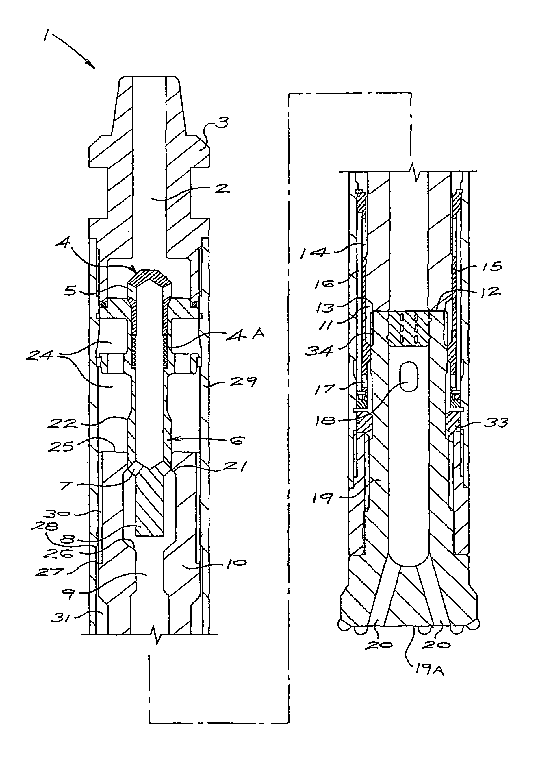
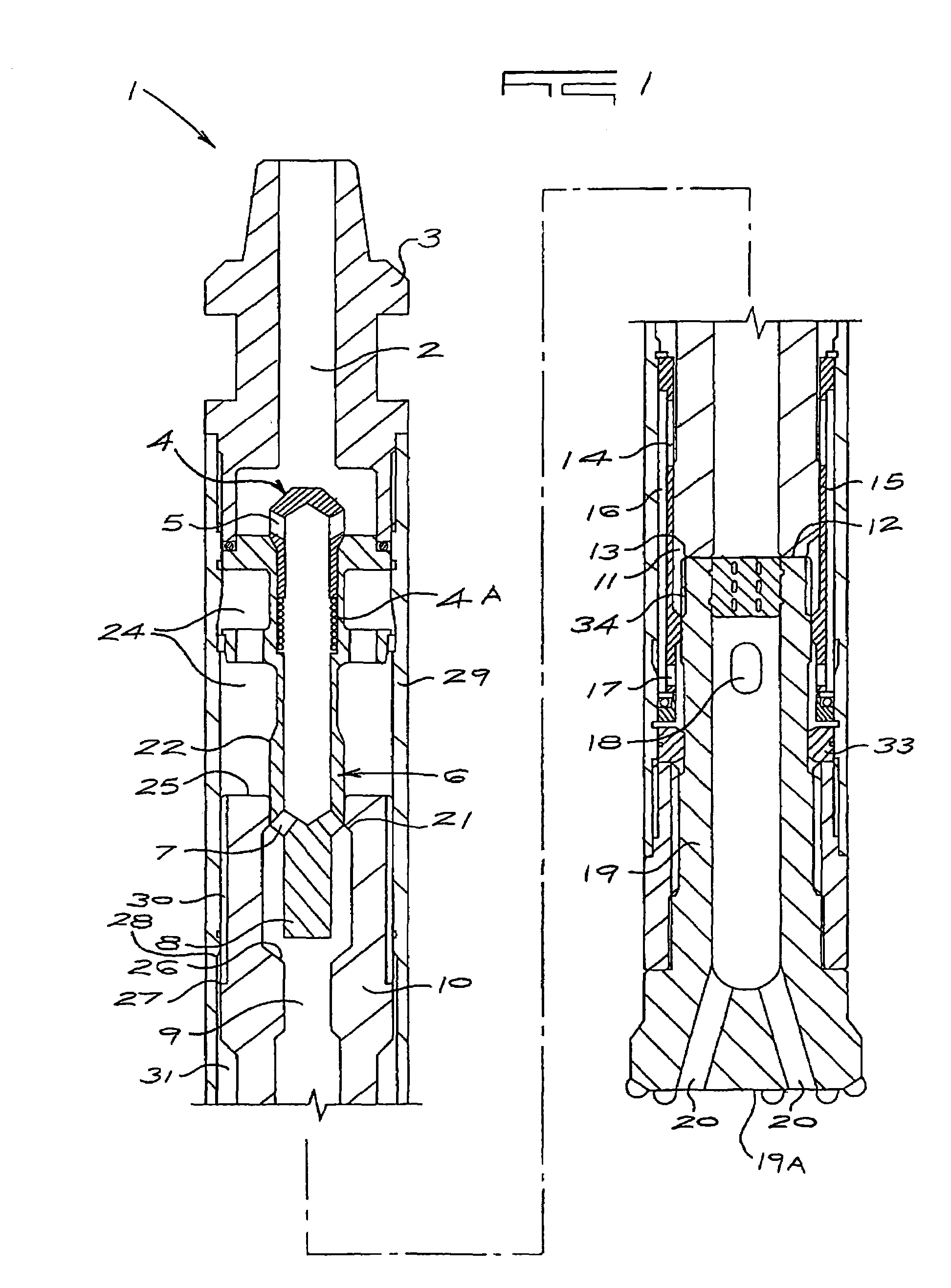
[0007]It is an object of this invention to provide a down-the-hole drill assembly which avoids the use of a foot valve tube.

Problems solved by technology

It will also weaken the walls of the piston and bit at its striking face.
This will cause a further restriction in the exhausting air of the hammer and will result in reducing the performance of the hammer.
Another problem experienced is the frequent breakage of the foot valve tube.
This results in down time for the driller as he has to pull the drill string out the hole, remove the bit from the hammer and replace the foot valve tube.

Method used


Image

  • Down-the-hole drill assembly
  • Down-the-hole drill assembly
  • Down-the-hole drill assembly

Examples


Embodiment Construction

[0017]As illustrated a down-the-hole drill hammer embodies the drill assembly (1) in accordance with this invention. The assembly (1) provides for lifting air to the lower chamber (11) below the piston (10) via the bore (9) of the piston (10) and the exhaust via the outside of the piston (10) and also via at least part of the outside of the bit (19) body. The exhaust air is then directed via opening (18) to the inside of the bit's drill face (19A) only because it is beneficial for flushing the drill cuttings out from underneath the bit face (19A). The function of the hammer is effective due to the fact that the compressed air flows directly through the bore (9) of the piston (10) with no deviation into the lower chamber (11) and causes the piston (10) to reciprocate faster thereby releasing more energy to the bit (19).

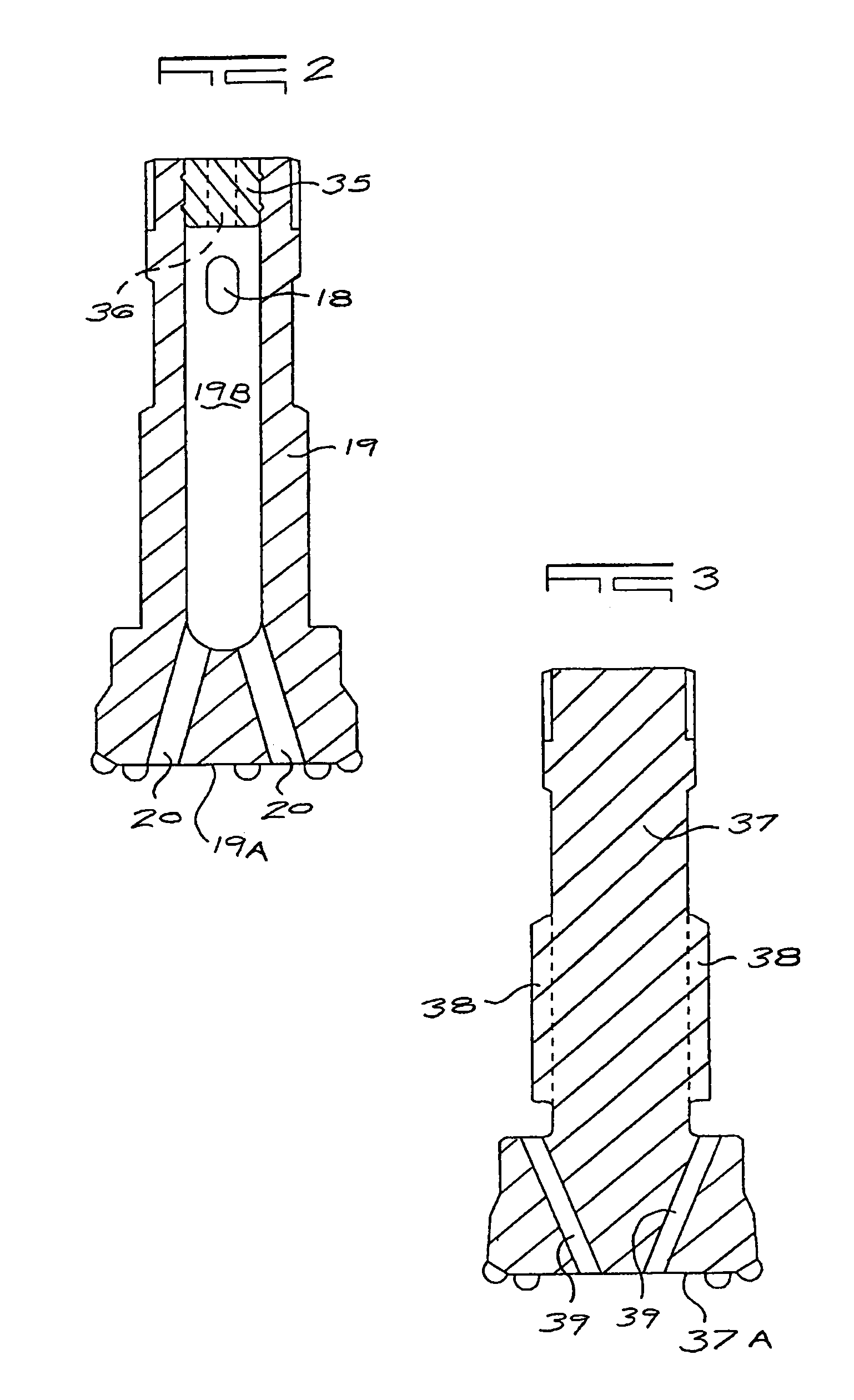
[0018]In this embodiment of the invention, the bit (19) has openings (18) extending transversely through the wall of the bit (19) into a blind bore (19B). The bore (19...


PUM

PropertyMeasurementUnit
Lengthaaaaaaaaaa

Abstract

The invention provides a down-the-hole drill assembly having exhaust passages from upper and lower chambers past the inner end of a bit and through the body of the bit to exit through the bit face. The construction of the assembly and bit obviates a foot valve tube from the head of the bit and the disadvantages associated with this component.

Description

FIELD OF THE INVENTION[0001]This invention relates to a down-the-hole drill assembly and more particularly to an assembly which eliminates the use of a foot valve tube.BACKGROUND TO THE INVENTION[0002]The common trend with valveless down-the-hole hammers is to have a drill bit with a replaceable foot valve tube protruding from the head of the bit at the striking face of the bit and piston. This foot valve tube extends into the bore of the piston and when the piston moves away from the bit the foot valve tube pulls out of the bore of the piston. Exhaust from the lifting or lower chamber takes place through the center of the foot valve tube to the atmosphere via the center bore of the bit.[0003]While the piston is striking the bit, and the bore of the piston is engaged with the foot valve tube, the upper chamber is exhausting through the bore of the piston through the center of the foot valve tube and out to the atmosphere via the bore of the bit.[0004]Exhaust from the lower and upper...

Claims


Application Information

Patent Timeline
IPC IPC(8): E21B4/14
CPCE21B4/14G07F7/005G07F9/00
Inventor GIEN, BERNARD LIONEL
Owner GIEN BERNARD LIONEL
Learn More