
Systems and methods of loading fluid in a prosthetic knee

a technology of prosthetic knees and fluids, applied in the field of prosthetic devices for loading fluid, can solve the problems of changing frictional characteristics, difficult control, and unreliable damping performan

Inactive Publication Date: 2007-04-03
OSSUR HF
View PDF178 Cites 114 Cited by
  • Summary
  • Abstract
  • Description
  • Claims
  • Application Information

AI Technical Summary

Benefits of technology

The vacuum fill technique enhances manufacturing speed, consistency, and safety by preventing fluid leakage and decomposition, resulting in a more reliable and durable prosthetic knee.

Problems solved by technology

Though dry friction brakes can generally provide a substantial torque range for their size, undesirably, they are often difficult to control.
After extended use, the frictional pads tend to wear, thereby changing the frictional characteristics of the brake and the torque response for a given commanded torque.
Disadvantageously, this can cause unreliable damping performance, and hence adversely affect the gait of the amputee and also cause discomfort to the amputee.
Consequently, dry friction brakes may need frequent servicing and / or replacement which undesirably adds to the cost.
Under high loading conditions, viscous torque brakes are susceptible to leakage of hydraulic fluid and possibly other damage due to excessive pressure build-up.
Disadvantageously, this can result in an irreversible state, since once the brake unit is overloaded it cannot return to normal.
Therefore, such a viscous torque brake for a prosthetic joint is prone to catastrophic failure, and hence can be unreliable and detrimental to the safety of an amputee.
In certain MR brakes and dampers, the interaction of the MR fluid with the device undesirably causes increased pressure, seal deterioration, or a combination of the two.
Another possible cause of these adverse effects is decomposition of the MR fluid.
Once the seals fail or the MR fluid decomposes, the prosthetic knee is no longer suitable for use.

Method used


Image

  • Systems and methods of loading fluid in a prosthetic knee
  • Systems and methods of loading fluid in a prosthetic knee
  • Systems and methods of loading fluid in a prosthetic knee

Examples


Embodiment Construction

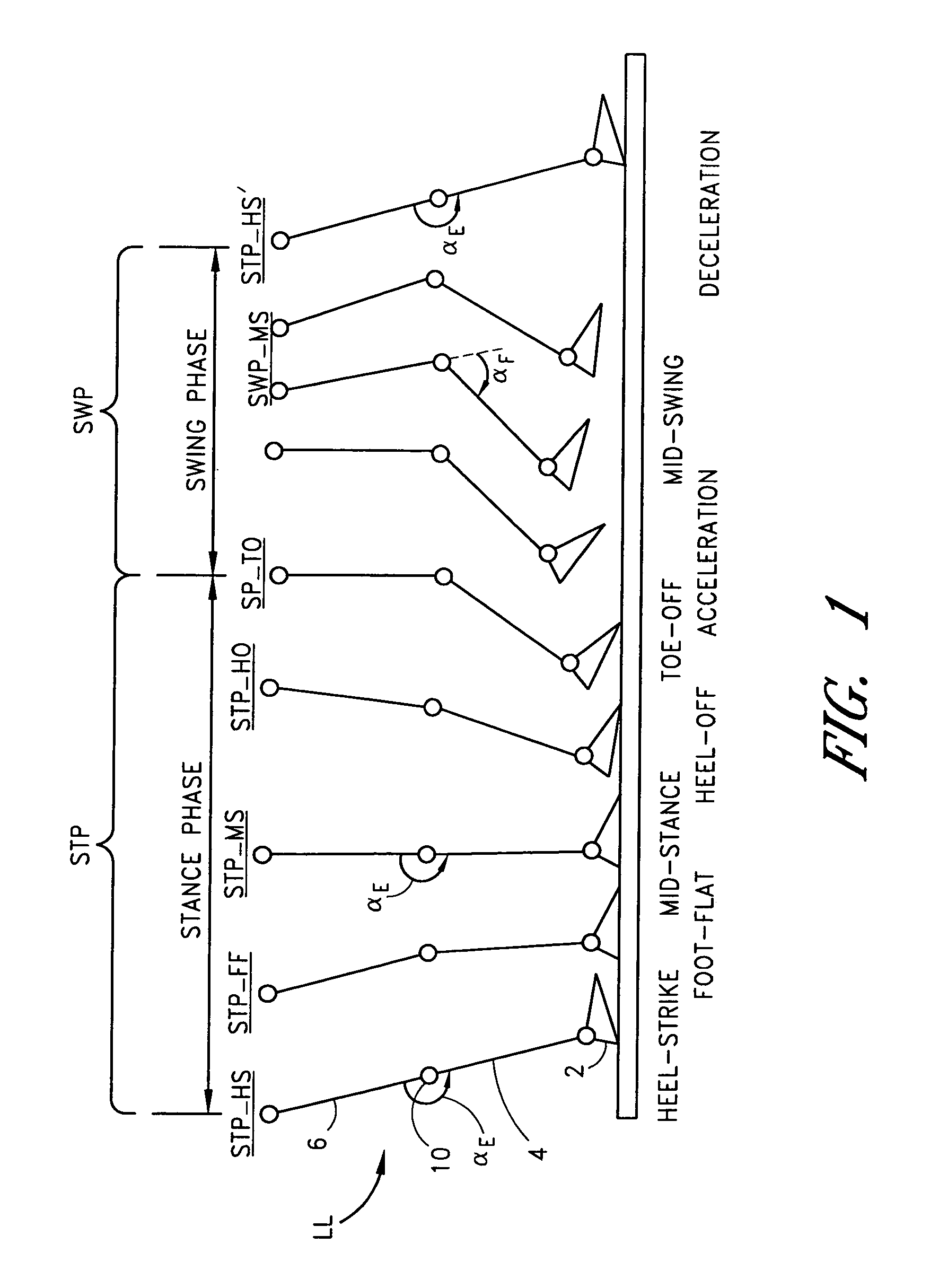
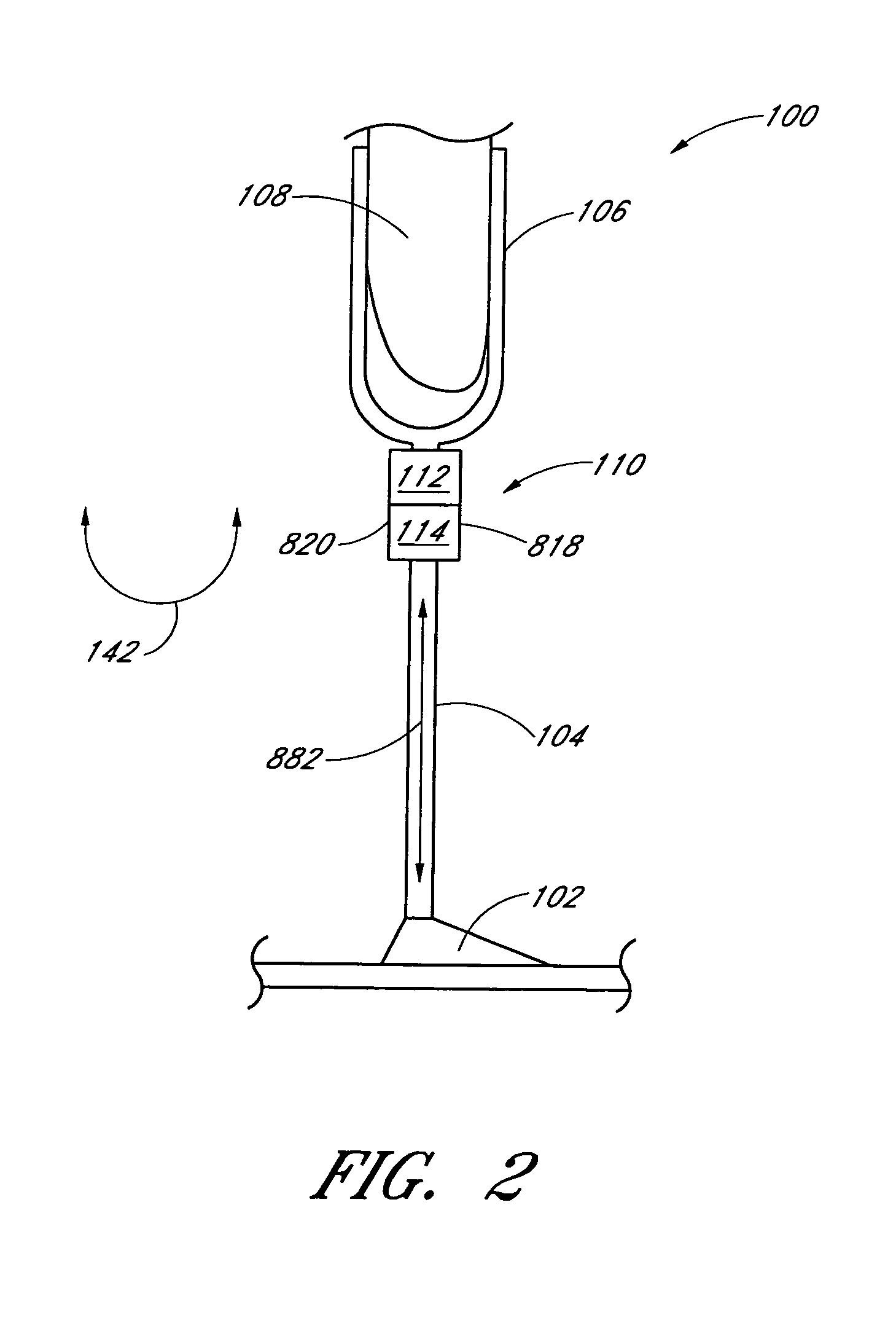
[0144]Some preferred embodiments of the invention described herein relate generally to prosthetic devices and, in particular, to magnetorheologically actuated controllable braking systems utilized in prosthetic knees for supporting an amputee that allow the amputee to move comfortably, safely and in a substantially natural and life-like manner in various dynamic and static states, terrains and topography.

[0145]While the description sets forth various embodiment specific details, it will be appreciated that the description is illustrative only and should not be construed in any way as limiting the invention. Furthermore, various applications of the invention, and modifications thereto, which may occur to those who are skilled in the art, are also encompassed by the general concepts described herein.

[0146]Understanding normal human walking / running provides the basis for the design and development of effective lower limb prostheses with controlled motion. Normal human locomotion or gai...


PUM

PropertyMeasurementUnit
sizeaaaaaaaaaa
volumeaaaaaaaaaa
flexion angle αFaaaaaaaaaa

Abstract

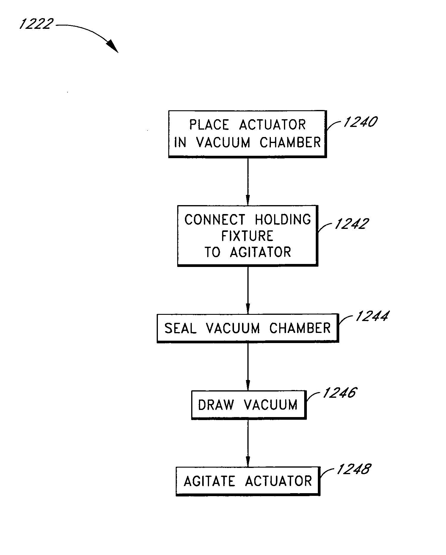
The invention in some embodiments relates to systems and methods of loading fluid in a prosthetic knee. A vacuum fill technique is utilized in one embodiment to load magnetorheological fluid within small gaps in a chamber of a prosthetic knee. Advantageously, this allows for an efficient loading scheme thereby desirably allowing for faster manufacturing speed. Another advantage is that the magnetorheological fluid is substantially uniformly distributed within the small gaps thereby desirably providing consistent production.

Description

RELATED APPLICATIONS[0001]This application is a continuation-in-part (CIP) of U.S. patent application Ser. No. 10 / 722,313 now U.S. Pat. No. 7,101,487, filed Nov. 25, 2003, which claims the benefit of U.S. Provisional Patent Application No. 60 / 467,722, filed May 2, 2003, the entirety of each one of which is hereby incorporated by reference herein.[0002]This application claims the benefit of U.S. Provisional Patent Application No. 60 / 569,512, filed May 7, 2004, and U.S. Provisional Patent Application No. 60 / 624,986, filed Nov. 3, 2004, the entirety of each one of which is hereby incorporated by reference herein.BACKGROUND OF THE INVENTION[0003]1. Field of the Invention[0004]The invention relates in one embodiment to loading fluid in prosthetic devices and, in particular, to a vacuum fill technique for efficiently and substantially uniformly loading a magnetorheological fluid in small gaps within a chamber of a prosthetic knee.[0005]2. Description of the Related Art[0006]Three types of...

Claims


Application Information

Patent Timeline
Patent Type & Authority Patents(United States)
IPC IPC(8): B65B1/04
CPCA61F2/5044A61F2/64A61F2/68A61F2002/5004A61F2002/5033A61F2002/5073A61F2002/6818A61F2002/704A61F2002/705A61F2002/7625A61F2002/7635A61F2002/7645A61F2002/769
Inventor BISBEE, III, CHARLES R.HSU, HENRY H.
Owner OSSUR HF
Learn More