
Multiple wavelength spectrometer

a multi-wavelength spectrometer and spectrometer technology, applied in the field of spectrometers, can solve the problems of cumbersome detection and/or monitoring of the spectral emission of light, single wavelength or very narrow detection, etc., and achieve the effect of reducing cross-talk

Inactive Publication Date: 2007-03-27
HONEYWELL INT INC
View PDF48 Cites 15 Cited by
  • Summary
  • Abstract
  • Description
  • Claims
  • Application Information

AI Technical Summary

Benefits of technology

The present invention provides a multiple wavelength spectrometer that can detect multiple wavelengths, and in some cases, across multiple wavelength bands. The spectrometer includes a first spectrometer and a second spectrometer, both of which may be secured relative to a substrate. The first detector is sensitive to the first tunable range of wavelengths and the second detector is sensitive to the second tunable range of wavelengths. The first and second tunable optical filters are adapted to detect the first and second tunable ranges of wavelengths, respectively. The first and second detector may be formed on the same substrate or separately and secured to the substrate. The first spectrometer may be an Ultra Violet (UV) spectrometer that includes a UV bandpass filter and a UV light sensitive detector. The second spectrometer may be a visible light spectrometer that includes a visible bandpass filter and a visible light detector. The UV bandpass filter and the visible bandpass filter may be selectively tunable by adjusting the separation gap. The multiple wavelength spectrometer may include a plurality of first and second spectrometers arranged in various configurations.

Problems solved by technology

A limitation of many of these optical filter / detector combinations is that they often can only detect a single wavelength or a very narrow band of wavelengths dictated by the selectively of the optical filter.
This can make it cumbersome to detect and / or monitor the spectral emission of light across a range of wavelengths and / or range of wavelength bands because numerous optical filters / detectors may be required, with each only detecting or monitoring a single or very narrow band of wavelengths.
In any case, this may help reduce cross-talk between the first and second spectrometers, as is sometimes a difficulty experienced with conventional Fabry-Perot optical systems.

Method used


Image

  • Multiple wavelength spectrometer
  • Multiple wavelength spectrometer
  • Multiple wavelength spectrometer

Examples


Embodiment Construction

[0024]The following description should be read with reference to the drawings, in which like elements in different drawings are numbered in like fashion. The drawings, which are not necessarily to scale, depict selected embodiments and are not intended to limit the scope of the invention. Although examples of construction, dimensions, and materials are illustrated for the various elements, those skilled in the art will recognize that many of the examples provided have suitable alternatives that may be utilized.

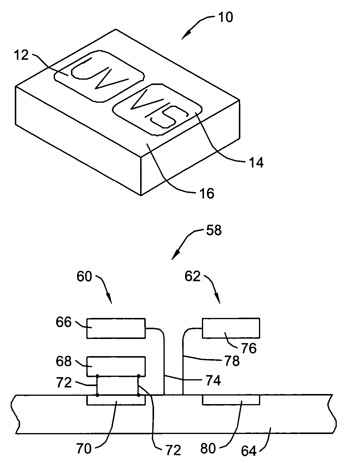
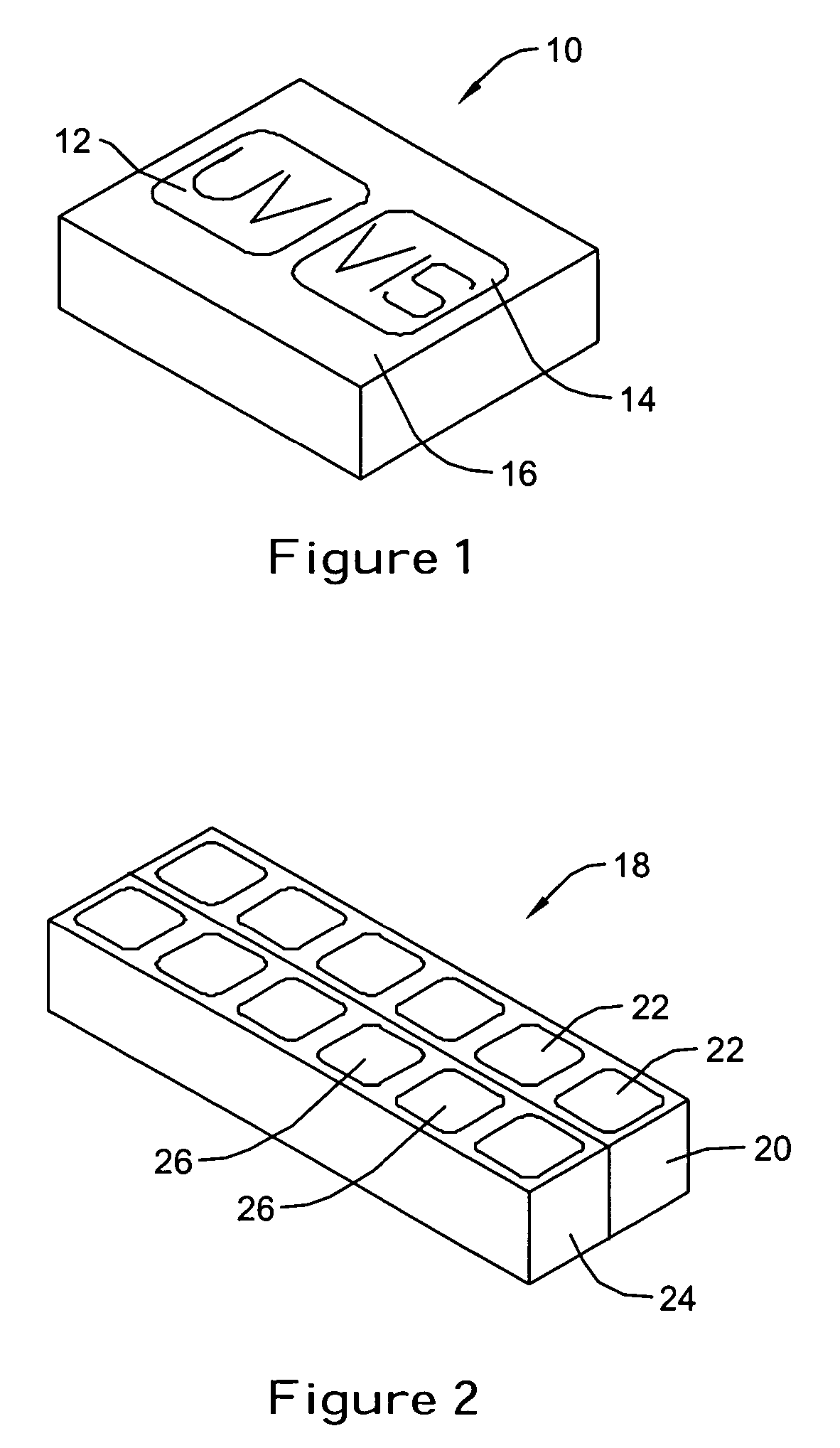
[0025]FIG. 1 is a diagrammatic perspective view of a multiple wavelength spectrometer 10 that includes an Ultra Violet (UV) spectrometer 12 that is configured to detect at least some wavelengths that fall within the UV spectrum and a visible light spectrometer 14 that is configured to detect at least some wavelengths that fall within the visible light spectrum. The UV spectrometer 12 and visible light spectrometer 14 can be formed upon or are otherwise disposed on a substrate ...


PUM

PropertyMeasurementUnit
wavelengthsaaaaaaaaaa

Abstract

Multiple wavelength spectrometers can be tuned to particular wavelengths. A dual wavelength spectrometer can include a spectrometer configured to detect at least some wavelengths that fall within the ultraviolet (UV) spectrum and a spectrometer configured to detect at least some wavelengths that fall within the visible spectrum. In some embodiments, a UV light spectrometer and a visible light spectrometer are disposed adjacent one another on a single substrate. A dual wavelength spectrometer can be used for analyzing bioaerosols, as well as for numerous other applications.

Description

[0001]This Application is a continuation-in-part application of U.S. patent application Ser. No. 10 / 100,298, filed Mar. 18, 2002 now U.S. Pat. 7,015,457, and entitled “SPECTRALLY TUNABLE DETECTOR”.GOVERNMENT SUPPORT[0002]This invention was made with government support under DARPA contract Number F10325. The government may have certain rights in the invention.TECHNICAL FIELD[0003]The present invention generally relates to spectrometers, and more particularly, to multiple wavelength spectrometers that can be used to sense more than one wavelength and / or band of wavelengths.BACKGROUND[0004]A number of spectrometers are known for selectively detecting light of various wavelengths. In particular, spectrometers are known for detecting individual or narrow wavelength bands of light, including wavelengths in the ultraviolet, visible, or infrared bands. In some cases, an optical filter is used in conjunction with a wide spectrum detector. The optical filter typically selects a particular wav...

Claims


Application Information

Patent Timeline
Patent Type & Authority Patents(United States)
IPC IPC(8): H01J40/14G01B11/27G01J3/36G01J3/427G01J5/20G02B5/28G02B26/00
CPCG01B11/272G01J3/36G01J3/427G01J5/20H01L31/0232G02B26/001H01L27/14621H01L31/02024G02B5/284H01L31/02162
Inventor COLE, BARRETT E.
Owner HONEYWELL INT INC
Learn More