
Projectile firing apparatus

a firing apparatus and projectile technology, applied in the direction of firing/trigger mechanism, ammunition, cartridge ammunition, etc., can solve the problems of significant time required to position, unsuitable application or utility of equipment, and relative slow rate of grenade delivery, etc., to achieve the effect of reducing the set-up tim

Inactive Publication Date: 2007-03-27
DEFENDTEX
View PDF33 Cites 3 Cited by
  • Summary
  • Abstract
  • Description
  • Claims
  • Application Information

AI Technical Summary

Benefits of technology

Enables rapid and precise firing of multiple projectiles at a selected target with reduced setup time, enhancing effectiveness in time-sensitive scenarios by allowing for efficient deployment and variable firing rates.

Problems solved by technology

Accordingly the relatively slow rate of delivery of grenades provides a significant constraint on the applications or utility of the equipment.
Barrels assemblies of the type described have the disadvantage that significant time may be required to position them for firing on a selected target.
This set-up time may be unsuitable for applications where time is of the essence, such as for setting up defences.

Method used


Image

  • Projectile firing apparatus
  • Projectile firing apparatus
  • Projectile firing apparatus

Examples


Embodiment Construction

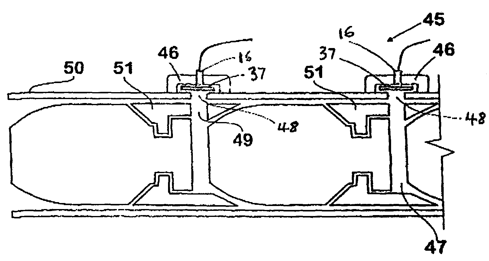
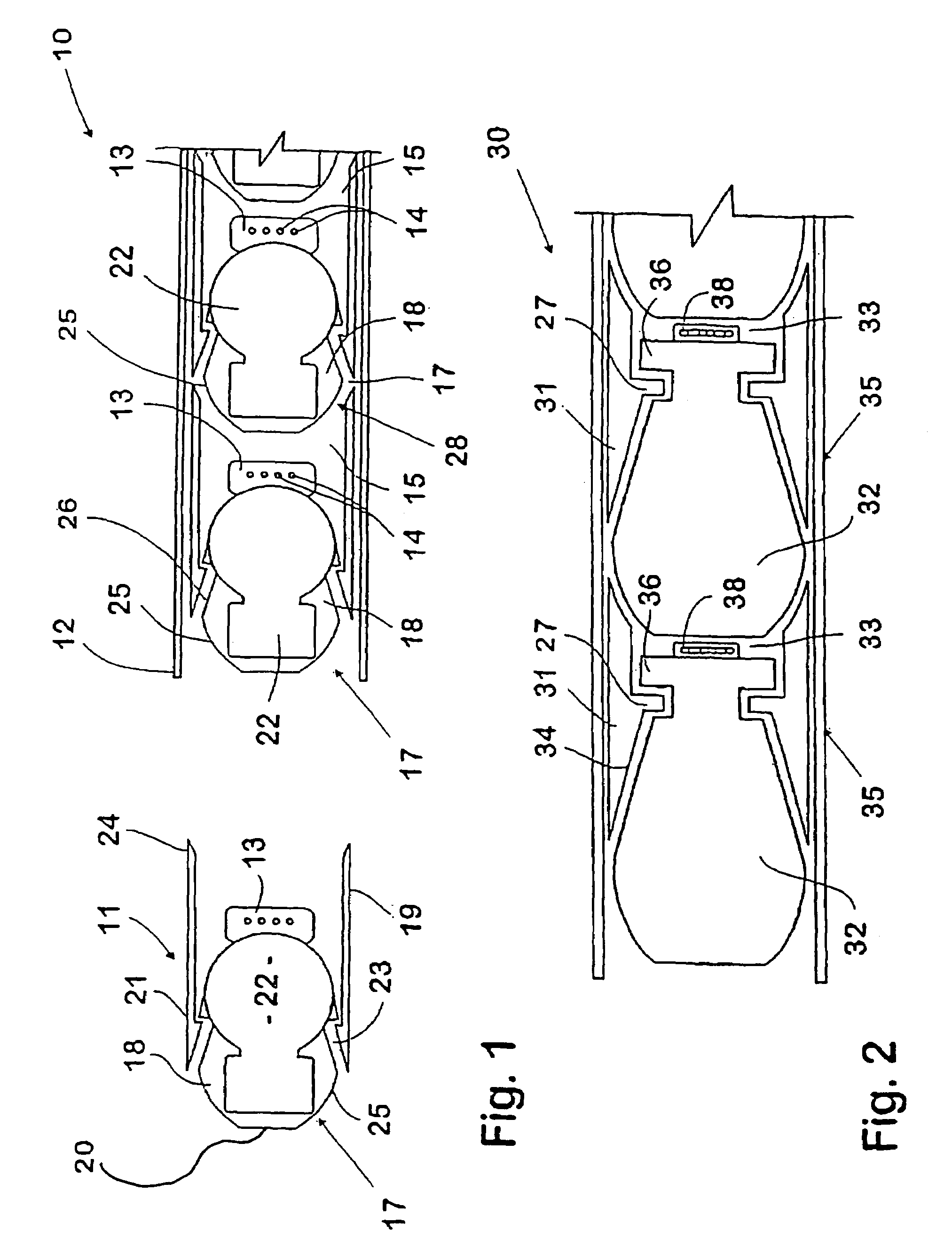
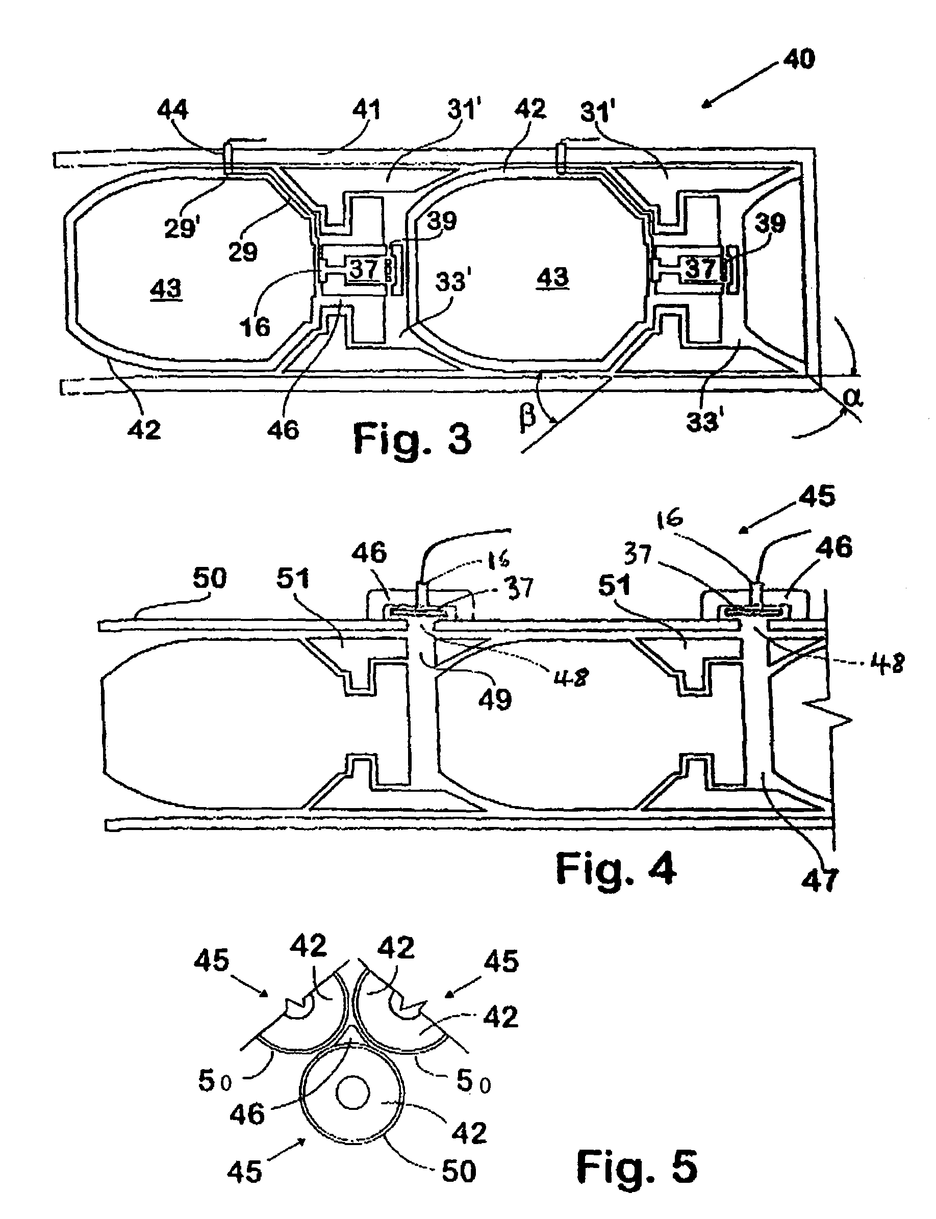
[0036]The barrel assembly 10 illustrated in FIG. 1 has multiple grenade carrying projectiles 11, for grenades of substantially known forms loaded or stacked in a rifled barrel 12 to impart spin upon firing for activating an arming device.

[0037]However a rupturable propellant cup or high pressure chamber 13 is fixed to the projectile 11 for discharging from the barrel with the projectile to clear the barrel 12 for firing the following projectile. This chamber 13 exhausts through ports 14 into the barrel space between the stacked projectiles 11, which space forms a low pressure chamber 15.

[0038]Each projectile 11 includes a projectile body 17, which in this embodiment is a grenade housing 18 housing a grenade 22, and a trailing sleeve or collar assembly 19 which is retained thereon for limited axial movement relative to a head part 20 of the grenade housing 18. The sleeve 19 has a leading end which tapers inwardly to an internal collar 21 which extends into a complementary shaped exte...


PUM


Abstract

A barrel assembly with a barrel is provided. The barrel comprises a plurality of external chambers containing respective propellant charges, a plurality of projectiles stacked nose to tail within the barrel and comprising respective expansion spaces for propellant gases, and a control system configured to ignite the propellant charges to create the propellant gases and propel the projectiles sequentially from the barrel. Each projectile has a corresponding external chamber and an expansion space and each chamber comprises a port that conveys propellant gas from the chamber into the expansion space for propulsion of the respective projectile.

Description

[0001]This application is a divisional of U.S. patent application Ser. No. 09 / 958,465, filed Feb. 26, 2002 now U.S. Pat. No. 6,722,252, which is the National Stage of International Application No. PCT / AU00 / 00297, filed Apr. 7, 2000; additionally, this application claims the priority to Australian Application No. PP 9613, filed on Apr. 7, 1999, and Australian Application No. PQ 3843, filed on Nov. 3, 1999, all of which are incorporated herein by reference.TECHNICAL FIELD[0002]This invention relates to projectiles and firing apparatus therefore and it has particular application to methods of and apparatus for firing projectiles for military use, although this invention is also applicable to civilian uses such as described in our simultaneously filed International application PCT / AU00 / 00296.BACKGROUND ART[0003]The military applications of firing projectiles are well known, such as firing grenades, firing radar deflecting chaff and missile decoy packages. In military applications such a...

Claims


Application Information

Patent Timeline
Patent Type & Authority Patents(United States)
IPC IPC(8): F41A19/64F41F1/00F41A19/65F41A21/06F41F1/08F42B5/03F42B39/26
CPCF41A21/06F41F1/08F42B39/26F42B5/035F41F1/085F41F1/00
Inventor O'DWYER, JAMES MICHAEL
Owner DEFENDTEX
Learn More