Method and apparatus for integrated undersampling

Active Publication Date: 2007-03-20
SYNOPSYS INC
View PDF3 Cites 9 Cited by
  • Summary
  • Abstract
  • Description
  • Claims
  • Application Information

AI Technical Summary

Benefits of technology

[0015]An advantage of undersampling, over full sampling, is that the sampling frequency can be arbitrarily low. To obtain this advantage, however, the input signal and sample clocks must be synchronous to a reference clock.
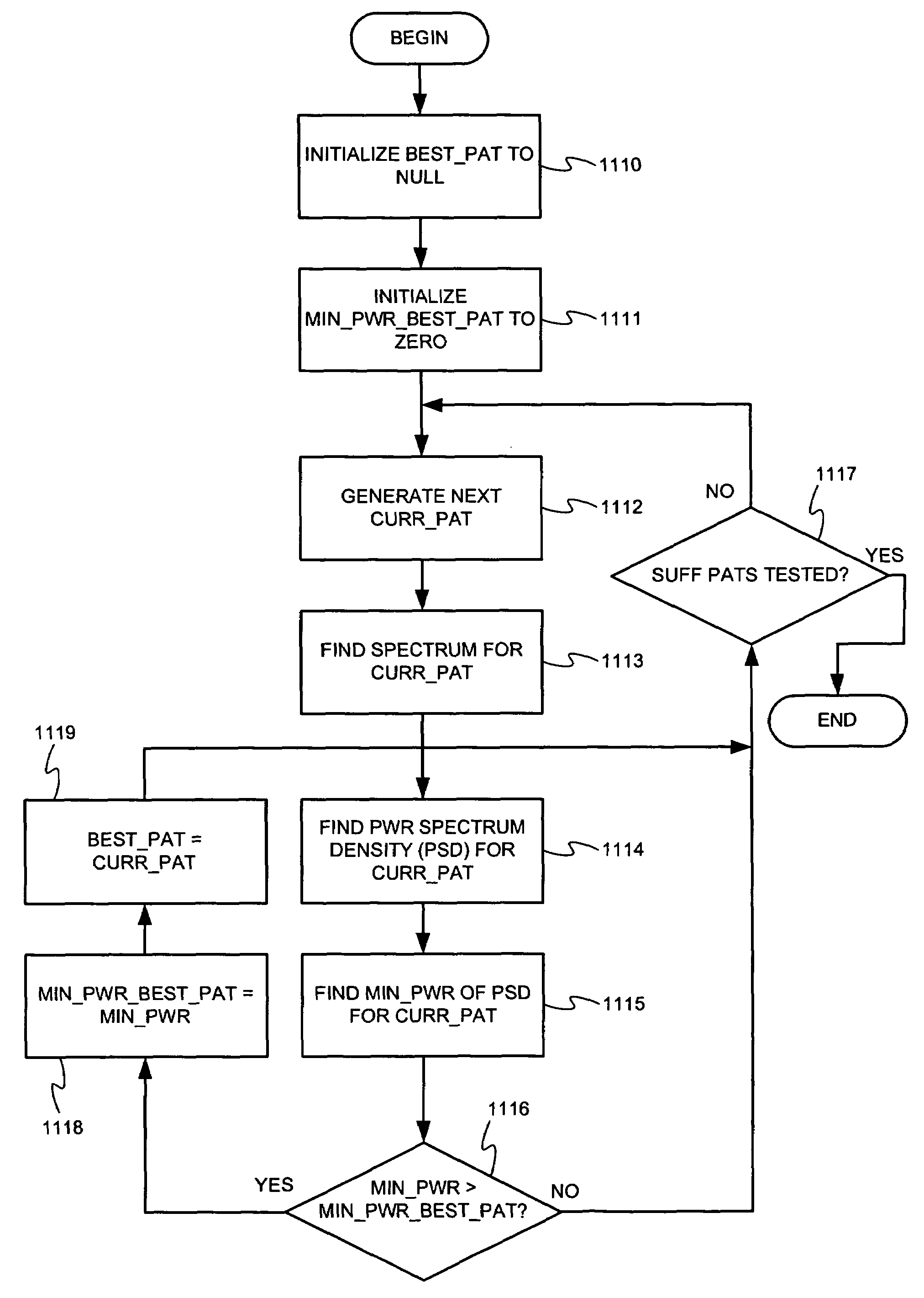
[0065]Since Tt(n) has periodic content of finite length, the space of potential patterns for Tt(n) can be searched for those patterns of content that maximize a particular metric. A metric that can be used, discussed further below, is maximizing the minimum power level, across the spectrum of interest. Based upon the highest frequency of interest, and the highest frequency which can reasonably be expected to be delivered to the receiver, a minimum effective sample rate at which to collect Rt(n) can be determined which avoids aliasing high frequency components down into the range of frequencies of interest.
[0067]The frequency resolution of Cf(n) can be increased by increasing the time duration of the pattern injected into the channel.
[0069]In general, to maximize the signal to noise ratio, a pattern can be selected for Tt(n) that maximizes the minimum power across the spectrum of interest. This constraint can be utilized by constructing a pattern generator that generates all permissible patterns, and weighting the desirability of each such pattern according to the metric of its minimum power level across the relevant portion of spectrum.

Problems solved by technology

First, the physical packaging, of the system whose receiver circuits are to be monitored, can be very dense and not admit of the physical insertion of a DSO probe.
Second, for high speed data transfer, the DSO probe itself can significantly change the characteristics of the channel and therefore the analog waveform to be measured.

Method used


Image

  • Method and apparatus for integrated undersampling
  • Method and apparatus for integrated undersampling
  • Method and apparatus for integrated undersampling

Examples


Embodiment Construction

[0088]Reference will now be made in detail to preferred embodiments of the invention, examples of which are illustrated in the accompanying drawings. Wherever possible, the same reference numbers will be used throughout the drawings to refer to the same or like parts.

[0089]

Table of Contents to Detailed Description1.Undersampling Overview2.Further Considerations For An Undersampling System3.Undersampling Implementation3.1.Undersampler 403, Internal Operation3.2.Trigger Unit Type 404, Internal Operation3.3.Example Computing Environment4.APLL 1004.1.Reference Clock Loop4.2.VCO 1034.3.Phase Mixer 1054.3.1.Overview4.3.2.Further Details4.4.APLL 405 of IC 16115.S-Parameter Capture5.1.DFT Determination5.2.Signal to Noise Considerations5.3.AC Coupled Receivers5.4.Example Pattern5.5.Example Search Procedure6.Glossary of Selected Terms

[0090]The present invention comprises techniques for undersampling, with the purpose of producing a histogram output, where the undersampler, and the receiver ci...


PUM


Abstract

An undersampling system can comprise an IC that has integrated, on the same physically contiguous IC, both an undersampler circuit and a receiver circuit whose input is to be monitored by undersampling. For a current phase of sample clocks relative to an input signal, the input signal is sampled until a sufficient number of samples are collected in a one dimensional histogram associated with the current phase. The phase of the sample clocks, relative to the input signal, can then be shifted. Such phase shift can be accomplished by a phase mixer. The phase shift can be small enough to provide sufficient resolution in a composite sampled image of the input signal. A mean value can be computed for each one dimensional histogram, resulting in a representation of the undersampled signal as a function of time that is suitable for further processing.

Description

CROSS REFERENCE TO RELATED APPLICATION[0001]This application is related to the following (currently pending) U.S. patent application that is herein incorporated by reference in its entirety:[0002]Title: “Method and Apparatus For Integrated Channel Characterization;[0003]Filing date: same as the present application;[0004]Inventor: Jeffrey Lee Sonntag;[0005]application Ser. No. 10 / 930,291.FIELD OF THE INVENTION[0006]The present invention relates to the collection of discrete time digital representations of analog signals, and more particularly to undersampling of such signals.BACKGROUND OF THE INVENTION[0007]During the design or maintenance of systems involving high-speed (e.g., 6.25 Giga-bit / sec) data transfer, it can be desirable to measure signals, as received by certain receiver circuits, as analog waveforms. Analog waveform measurement can be approximated by capturing a series of discrete time samples of a signal and converting the samples into digital values. Analog waveform mea...

Claims


Application Information

Patent Timeline
IPC IPC(8): G01R13/00
CPCG01R19/2509G01R13/345G01R27/28
Inventor SONNTAG, JEFFREY LEE
Owner SYNOPSYS INC
Why Eureka
Try Eureka